Download
1 / 15
150 likes | 285 Views
16.317: Microprocessor System Design I. Instructor: Dr. Michael Geiger Spring 2012 Lecture 26: Exam 2 Preview. Lecture outline. Announcements/reminders Lab 3 posted; report due 4/11 Today: Exam 2 Preview General exam info Topics covered Instructions Bit test/scan instructions

E N D
16.317: Microprocessor System Design I Instructor: Dr. Michael Geiger Spring 2012 Lecture 26: Exam 2 Preview
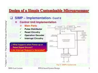
Lecture outline • Announcements/reminders • Lab 3 posted; report due 4/11 • Today: Exam 2 Preview • General exam info • Topics covered • Instructions • Bit test/scan instructions • Flag control instructions • Compare instructions • Jump and loop instructions • Subroutine instructions • Protected mode • Basic characteristics • Memory accesses • Virtual memory • External interfacing Microprocessors I: Exam 2 Preview
Exam 2 notes • Allowed • One 8.5” x 11” double-sided sheet of notes • Calculator • No other notes or electronic devices (phone, laptop, etc.) • Exam will last 50 minutes • Covers all lectures after Exam 1 (Lec. 15-25) • Format similar to Exam 1, but shorter • 1 multiple choice question • Covers topics not addressed in practice problems • 2-3 short problems to solve/code sequences to evaluate Microprocessors I: Exam 2 Preview
Review: Bit test/scan, flag control • Bit test instructions • Check state of bit and store in CF • Basic test (BT) leaves bit unchanged • Can also set (BTS), clear (BTR), or complement bit (BTC) • Bit scan instructions • Find first non-zero bit and store index in dest. • Set ZF = 1 if source non-zero; ZF = 0 if source == 0 • BSF: scan right to left (LSB to MSB) • BSR: scan left to right (MSB to LSB) • Flag control instructions • Initialize carry flag to 0 (CLC), 1 (STC), or ~CF (CMC) • Set (STI) or clear (CLI) interrupt flag • Transfer flags to (LAHF) or from (SAHF) register AH Microprocessors I: Lecture 16
Review: Compare, set on condition • CMP D, S • Flags show result of (D) – (S) • Assumes signed computation • ZF = 1 D == S • ZF = 0, (SF XOR OF) = 1 D < S • ZF = 0, (SF XOR OF) = 0 D > S • Condition codes: mnemonics implying certain flag conditions • SETcc D • Sets single byte destination to all 1s (FFH) if condition true; all 0s (00H) if condition false • Can be used to build up complex conditions Microprocessors I: Lecture 17
Review: jump instructions • Two general types of jump • Unconditional: JMP <target> • Always go to target address • Conditional: Jcc <target> • Go to target address if condition true • Target can be: • Intrasegment: same segment; only IP changes • Add constant 8/16 bit offset, or • Replace IP with 16 bit value from register/memory • Intersegment: different segment; CS/IP both change • Target is 32-bit value • Upper 16 bits overwrite CS; lower bits overwrite IP • Jump applications • Conditional statements (if/else) • Loops (pre-/post-tested) Microprocessors I: Lecture 18
Review: loop instructions • Loop instructions • Combines CX decrement with JNZ test • May add additional required condition • LOOPE/LOOPZ: loop if ((CX != 0) && (ZF == 1)) • LOOPNE/LOOPNEZ: loop if (CX != 0) && (ZF == 0)) Microprocessors I: Lecture 19
Review: subroutines • Subroutines: low-level functions • When called, address of next instruction saved • Return instruction ends routine; goes to that point • May need to save state on stack • 80386 specifics • CALL <proc>: call procedure • <proc> can be label (16-/32-bit imm), reg, mem • RET: return from procedure • Saving state to stack: push instructions • Store data “above” current TOS; decrement SP • Basic PUSH stores word or double word • Directly storing flags: PUSHF • Storing all 16-/32-bit general purpose registers: PUSHA/PUSHAD • Restoring state: POP/POPF/POPA/POPAD Microprocessors I: Lecture 20
Review: protected mode • Protected mode • Supports memory management, multitasking, protection • Changes in control/flag registers, IP, memory accesses • Selectors: pointers into descriptor tables • Contains requested privilege, global/local, and table index • Descriptors: provide info about segments • 8 bytes in length • 4 bytes: base address • 2 bytes: limit (max offset within segment) • Segment size = (limit + 1) bytes • 2 bytes: access info (privilege, R/W, executable, etc.) Microprocessors I: Lecture 21
Review: Protected mode (cont.) • Local memory access • Selector indicates access is global (TI == 1) • LDTR points to LDT descriptor in GDT • Actual base, limit of LDT stored in LDTR cache • Index field in selector chooses descriptor from LDT • Descriptor addr = (LDT base) + (selector index * 8) • Descriptor provides starting address of segment • Interrupt descriptors • Provide starting address, length of interrupt service routines • Limited to 256 descriptors • Stored in IDT; IDTR holds base/limit of IDT • Task switching • Task register (TR): selector for current task state segment (TSS) • TSS stores all state (register values) for current task • Task switch: jump/call that changes TR; old TSS saved and new one loaded Microprocessors I: Lecture 22
Review: Virtual memory • Virtual memory • Allows programmer to see more memory than system has • Allows program to function with variable amount of memory • Address undergoes translation from virtual address to physical address • Page table handles translation • Indexed by page #; provides physical frame # • Page table can have multiple levels to save space • TLB caches translations to save time • 80386 specifics • Virtual address: 46 bits • Upper 14 bits of selector + 32 bits of offset • Physical address: 32 bits • If just using segments, physical address = linear address • If using paging (4 KB pages), linear address used to index 2-level page table Microprocessors I: Lecture 23
Review: Interfacing • Processor interfaces generally contain • Address outputs: specify location • Data input/outputs: data to be read/written • Control signals • Data size • Transaction type (read/write, privilege level, etc.) • Handshaking signals • Request/acknowledge pairing • Controls timing of read/write operations • Bus control • Interrupt interface • Some contain special purpose signals • DMA interface • Coprocessor interface Microprocessors I: Exam 2 Preview
Review: 80386 Interfaces (Fig 9.3, p. 376) A2-A31 HOLD DMA interface HLDA BE0-BE3 D0-D31 INTR Interrupt interface W/R NMI Memory/ IO interface D/C RESET M/IO ADS PEREQ READY Coprocessor interface BUSY NA ERROR LOCK BS16 Microprocessors I: Lecture 25
Review: bus cycle • Driven by system clock • Valid address, control signals placed on bus • Cycle concludes when acknowledged by external logic Microprocessors I: Lecture 25
Next time • Exam 2 • Remember, only 1 note sheet, calculator (no cell phones as calculators) • Please be on time! Microprocessors I: Exam 2 Preview