Download
1 / 48
480 likes | 698 Views
Video Phone System Design. Brad Murray Greg Lefty Mike Halfen. ECES 488 Spring 2000. Introduction. Unique Design Features Button Scheme “Streamed Video” Time Stamp From Caller ID. User Defined System Constraints. Require external power supply Plug directly to Telco Jack

E N D
Video Phone System Design Brad Murray Greg Lefty Mike Halfen ECES 488 Spring 2000
Introduction Unique Design Features • Button Scheme • “Streamed Video” • Time Stamp From Caller ID
User Defined System Constraints • Require external power supply • Plug directly to Telco Jack • Maximum message length of 60 seconds • Maximum of 30 messages • When message memory is filled, the oldest message is erased. • Standalone device
Technical System Constraints • Audio Sample Rate = 8K samples/second • Audio Memory Requirement 384 Kbyte/message • QCIF Standard Video Format (176 x 144) 304 Kbit/ frame Compressed (20:1) = 15.2 Kbit/frame At 1 frame/sec = 114 Kbyte/message • Total Message Storage - 14.9 MB • Additional DSP Data/Table Memory = 64K
Design Options • Available Hardware Options • Off the shelf IC • DSP/Microcontroller • FPGA • ASIC • Determining Factors • Design Cost • Production Cost • Flexibility
The Competition • Market segmented • Video calls over IP • Dominant segment • Extremely cheap ($70 for camera/software) • Hardware often consists only of digital camera • Software driven design • Computer, network connection required • Video over telephone • TV / Monitor products • Still cheap ( < $300) • Display Integrated devices • Most Expensive
Display Integrated Videophones • Common features • H.324 compliant • Able to send minimum of 7 frames/sec (up to 15!) • Use of QCIF standard (176 x 144 pixel picture transmitted) • Camera electronically adjustable: zoom, pan, tilt • 4” LCD Display: adjustable picture quality and size • Average retail price: $600 • Manufacturers • Aiptek • Cheap!! ~$450 at Amazon.com • Basic features only • MCF Enterprises (~$600) • Picture in Picture • Advanced standard telephone features • Answering machine (voice only) • Redial & Number Memory
Display Integrated Videophones • Other Manufacturers • 8x8 • Led market in this segment • Discontinued telephone products • Now manufactures H.323 products • Video conferencing over I.P. • Provides chip sets and development solutions for H.324 • Panasonic • Only major electronics manufacturer in this market • Same features as Aiptek, 8x8 • Priced 2 - 3 times higher ($1150!!)
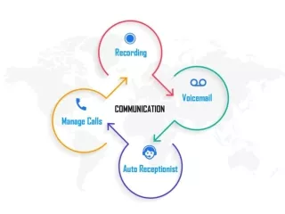
Digital Camera Button Button Button Button Button System Overview LCD Display 9 0 LCD Controller # * Cancel RAM 1 2 3 4 5 6 7 8 Microphone DSP (video processing) BUTTONS FLASH De-bounce Circuitry DSP (audio Processing) A/D Converter Speaker Audio Amp D/A Converter Phone Line (POTS) Modem
Components • LCD Display • Digital Camera • Analog to Digital Converter (ADC) • Digital to Analog Converter (DAC) • Modem DSP • Video DSP • Memory
Requirements • 320 x 240 resolution 8 bit color • DSP Controlled • Low Cost LCD Display Market Analysis
Requirements • 320 x 240 resolution 8 bit color • DSP Controlled • Low Cost Digital Camera Market Analysis
Requirements • 8,000 Samples per Second • 8 bits per Sample • Low Cost ADC / DAC Market Analysis
Requirements • Maintain 30 Messages • 60 Seconds each • Communicate with Video DSP • Large Flash Memory for Message Storage • Small Memory for Program and Data Space • Low Cost Memory Market Analysis
Requirements • Communicate with Video DSP • Process Audio (ADC/DAC) • Communicate with Modem • H.324 Compliance • Mux/Demux modem data • H.223 Protocol • Process Inter-terminal communication • H.245 Protocol • Low Cost Audio DSP
Requirements • Communicate with Modem DSP • Receive and Compress Camera Data • Decompress and Send LCD Data • Encode/Decode Video Data • H.263 Protocol for H.324 Compliance • Store and Retrieve Messages Video DSP
DSP Evaluation • Speed • # of Interfaces • Serial • Parallel • Cost • Bit capability • ALU • Bus width • Registers
DSP Market Analysis TI TMS320VC35402
Bus Interfaces • Serial Interface • Digital Camera • AD/DA converters • HPI Interface • DSP – DSP communication • Parallel • Memory • LCD Controller
Serial Port Interface: Transmitting 1 2 3 4 5 6 7 8 9 10 CLKX FSX Frame Sync TXM Next transmission may begin DX D0 D1 D2 D3 D4 D5 D6 D7 Next transmission may begin MSB LSB XINT Next transmission may begin Clock 1: Data is loaded into output register Clock 2, rising edge: Frame sync signal is generated Clock 2, falling edge: Interrupt generated to indicate transmission has begun Clock 3..10: One data bit is sent on each rising clock edge Clock 9: New data may be loaded into output register Clock 10: If output register was loaded, frame sync signal is generated
Serial Port Interface: Receiving 1 2 3 4 5 6 7 8 9 10 CLKR FSR Frame Sync RX Next transaction may begin DR D0 D1 D2 D3 D4 D5 D6 D7 Next transaction may begin MSB LSB RINT Clock 1: Frame sync is generated Clock 2..9: One data bit is sampled on each falling clock edge Clock 9, falling edge: Interrupt generated to indicate data is ready in receive register Clock 10, rising edge: Frame sync may be generated for next transaction Clock 10: If frame sync generated, MSB of next byte is received
Inter-DSP Communication: Parallel Bus to HPI Interface Bus Master DSP Slave DSP HA 14:0 ADDR 14:0 DATA 15:0 HD 15:0 /IS /HDS R-/W R-/W GPIO /HDS READY HREADY Slave is mapped into master’s IO space
HPI Transaction Timing Diagrams: Write: Read: /HCS HR-/W HA[15:0] 15-bit address 15-bit address HPID contents HPID contents HD[15:0] HREADY
Push-button Interface Video Picture displayed in this box. Menu options listed in boxes to the right and below. Vert. 1 • Implements user interface • Software definable functions • Greatly reduces number of physical buttons needed • Menu of options displayed on-screen Vert. 2 Vert. 3 Vert. 4 Vert. 5 Hz. 1 Hz. 2 Hz. 3 Hz. 4 Hz. 5 Hz. 6 Hz. 7 Hz. 8
LCD Display Vert. 1 Button Vert. 2 Button Vert. 3 Button Vert. 4 Button Vert.5 Button Hz 1 Hz 2 Hz 3 Hz 4 Hz 5 Hz 6 Hz 7 Hz 8 Button Button Button Button Button Button Button Button Push Button Interface • Physical buttons • 13 buttons used • Buttons needed for a single function placed together • Keeps the interface easy to use • Making a call requires 0-9, #, *, and “Cancel” • Placed around LCD screen • Adjacent to on-screen menu options
Interface Flow Example (1): 1: Initial Menu: 2: “Place Call” is pressed Place Call 9 Play Messages 0 Greeting Options # * System Options Cancel Cancel 1 2 3 4 5 6 7 8 4: a) Sequence completed-- dials b)”Cancel” pushed – returns (1) 3: Numbers/Symbols pushed (displayed on-screen as pushed) 1 216 368 200 9 1 216 368 2000 Dialing… 9 0 0 # # * * Cancel Cancel 1 2 3 4 5 6 7 8 1 2 3 4 5 6 7 8
Interface Flow Example (2): 1: Initial Menu: 2: “Place Messages” is pressed Place Call Place Call Play Messages Play Messages Greeting Options Greeting Options System Options System Options Cancel Cancel Play Message Previous Message Next Message Erase Message Current Message: 4 of 25 Received: 6:30 PM 4/27/00 3: b) “Play Message”: Plays current message c) “Cancel” : Returns to 1 d) “Greeting Options” displays Greeting menu 3: a) “Erase Message” pushed Message Erased. Place Call Play Messages Place Call Greeting Options Play Messages System Options Greeting Options Cancel System Options Play Message Previous Message Next Message Erase Message Current Message: 4 of 24 Received: 6:30 PM 4/27/00 Cancel Record Greeting View Greeting Disable Video Greeting Select Active Greeting Greeting 3 is currently active
Idle Recording Messages Playing Messages Record Outgoing Message Calling Communicating Flow Chart Level 1 Hang up Time out/ disconnect Time-out/button press User Presses Record Greeting User Selects Play Messages User Presses Answer Phone User Presses Call Button No messages/disconnect 4 Rings Code Entered Phone Answers
Get First Message From Flash Decompress Audio Remote Checking? Insert Delay Decompress Video Play Audio Play Video Next Message Previous Message Delete Message Repeat Message Time Out/ Disconnect/ User Presses Stop Get Next Message Does Message Exist? Get Message Flow Chart Level 2: Playing Messages Remote Code Entered User Presses Play Yes No No Yes
Digital Connection? Get Audio/Video Out Message Get Voice Out Message Send Play Out Message Done? Done? Code Entered? Receive Phone Data Packet Code Entered? Receive Voice Message Extract Audio/ Video Data Store In Flash Play Messages Play Messages Done? Store In Flash Done? Time Out? Time Out? Flow Chart Level 2: Recording Messages 4 Rings Yes No No No No No Yes Yes Yes No No Yes No No Yes Yes
Dialtone? Connected? Communication Cancel Button Pressed User Presses 0-9, #, * Send Tone Flow Chart Level 2: Calling Call Button Pressed No Yes Yes No No Yes
Get Audio Get Video Compress Audio Compress Video Cancel Button Pressed? Time Out? Flow Chart Level 2: Record Outgoing Message Record Button Pressed Yes No Yes No
Establish Digital Communication/ Modem Training Initialization Idle Hangup? Is Sender? Get Phone Data Get Audio Get Video Unpack A/V From H.324 Compress Audio Compress Video Decompress Audio Decompress Video Pack A/V into H.324/ Add Audio Delay Insert Requested Delay Send Over Phone Play Video Play Audio Flow Chart 2: Communication Answer Phone Other End Picks Up Yes No Yes No
Answer == TRUE Record_Greeting == TRUE State = 6.0 State = 3.0 Phone_Answer == TRUE State = 6.0 Disconnect == TRUE State = 1.0 End_Recording == TRUE || Rec_Msg_Packets > OUT_MSG_MAX State = 1.0 Make_Call == TRUE State = 5.0 Disconnect == TRUE || Rec_Msg_Time_Out == TRUE User_Cancel == TRUE State = 1.0 State = 1.0 Rings == 4 State = 2.0 No_Messages == TRUE || Disconnect == TRUE || Stop_Playback == TRUE Play_Msgs == TRUE State = 4.0 State = 1.0 Valid_Code_Entered == TRUE State = 4.0 State Machine Diagram Communicating 6.0 Record Outgoing Greeting 3.0 Idle State 1.0 Calling 5.0 Record Caller Msg 2.0 Playback Message 4.0
Make_Call == TRUE State = 5.0 Ring_Detect == TRUE Record_Greeting == TRUE State = 1.2 Rings < 4 State = 3.0 State = 1.2 Ringer_Timeout == TRUE State = 1.1 Play_Msgs == TRUE State = 4.0 Rings == 4 State = 2.0 Answer == TRUE State = 6.0 Idle State 1.0 Diagram Listen For First Ring 1.1 Count Rings 1.2
More_Data_Available == TRUE Packet Retrieved State = 2.1 State = 6.3 Valid_Code_Entered == TRUE State = 4.0 More_Data_Available == FALSE && Flash_Full == TRUE More_Data_Available == FALSE && Flash_Full == FALSE State = 2.2 State = 2.3 Done_Overwriting == TRUE State = 2.3 Flash_Ready == TRUE State = 6.4 Disconnect == TRUE || Rec_Msg_Time_Out == TRUE State = 1.0 Packet_Stored == TRUE Data_Received == TRUE State = 6.4 Packet_Type = MSG State = 2.4 Record Caller Msg State 2.0 Diagram Retrieve Outgoing Greeting 2.1 Send Data 6.3 Overwrite Oldest Message 2.2 Get Next Available Msg Location 2.3 Receive Data 6.4 Store Packet 2.4
Read_Data_Buffer == FULL State = 3.2 End_Recording == FALSE && Rec_Msg_Packets < OUT_MSG_MAX Rec_Msg_Packets++ State = 7.0 AV_Compression == COMPLETE Packet_Type = OUTGOING State = 2.4 End_Recording == TRUE || Rec_Msg_Packets >= OUT_MSG_MAX State = 1.0 Record Outgoing Greeting State 3.0 Diagram Get Audio / Video 7.0 Compress Audio and Video 3.2 Store Packet 2.4
Play_Msgs == TRUE && Msg_Retrieved == TRUE Msg_Selection == REPEAT Valid_Code_Entered == TRUE && Msg_Retrieved == TRUE State =4.1 State = 4.4 State = 4.2 Audio_Decompression == COMPLETE Decompression == COMPLETE State =4.3 State =4.5 Msg_Selection == NEXT Msg_Played == TRUE Audio_Sent == TRUE Message_To_Play++ State =4.1 State =4.6 State =4.6 No_Messages == TRUE || Disconnect == TRUE || Stop_Playback == TRUE Msg_Selection == PREVIOUS Message_To_Play-- State =4.1 State = 1.0 Playback Messages State 4.0 Diagram Retrieve Message 4.1 Decompress Audio 4.2 Decompress Audio And Video 4.4 Play Audio 4.3 Play Audio And Video 4.5 Message Selection 4.6
User_Cancel == TRUE State = 1.0 Number_Entered == TRUE Ringing == FALSE State = 5.2 State = 5.1 Ringing == TRUE State = 5.3 Phone_Answer == TRUE State = 6.0 Calling State 5.0 Diagram Waiting For User Input 5.1 Send Tone 5.2 Wait For Pickup 5.3
Parameters_Set == TRUE State = 7.0 Read_Data_Buffer == FULL Parameters_Set == TRUE State = 3.2 State = 6.2 Disconnect == TRUE State = 1.0 Outgoing_Data_Present == TRUE State = 6.2 Data_Reception_Complete == TRUE Incoming_Data_Present == TRUE State = 6.2 State = 6.4 Data_Transmission == TRUE State = 7.0 Outgoing_Data_Present == TRUE Packet_Received == TRUE State = 6.3 State = 4.4 Decompression == COMPLETE State =4.5 Communicating State 6.0 Diagram Negotiate Setup 6.1 Get Audio / Video 7.0 Compress Audio and Video 3.2 Wait For Data 6.2 Receive Data 6.4 Decompress Audio And Video 4.4 Send Data 6.3 Play Audio And Video 4.5
Caller ID – Physical Layer Physical Layer • 8 bit Characters Transmitted Asynchronously • One Start Bit, Between One and Ten Stop Bits • 1200 baud FSK Modulated Data Format S2 M B7 B6 B5 B4 B3 B2 L S1 S1 – Start Bit S2 – Stop Bit M – Most Significant Bit L – Least Significant Bit B* - Bit Numbers 2 to 7 Most Significant Octet is Transmitted First
Channel Seizure Mark Signal Message Type Message Length Message Presentation Layer Checksum Caller ID – Datalink Layer 80 – 262 ms > 45 ms ~ 9.8 ms ~ 9.8 ms 0 – 2488 ms ~ 9.8 ms 96 – 315 bits > 55 bits 8 bits 8 bits 0 – 2040 bits 8 bits Channel Seizure – Phasing Pattern of Alternating 1’s and 0’s Mark Signal – A Series of Mark Bits (1’s) Message Type – Application Dependent Checksum – 2’s Complement Sum of all Bytes From “Message Type” Word
Parameter Type Parameter Length Parameter Byte(s) Parameter Type Parameter Length Parameter Byte(s) Caller ID – Presentation Layer … Parameter Type 1 – Time & Date 2 – Calling Line Directory Number (DN) 3 – Called Directory Number 4 – Reason for Absence of DN 7 – Caller Name / Text 8 – Reason for Absence of Name 17 – Call Type 19 – Network Message System Status
Msg 1 Msg 2 Msg 3 Msg 4 Msg 5 Msg 6 Msg 7 … Msg 30 Messaging Msg Lookup Table Next Available Msg Flash Memory Msg 3 Msg 4 Msg 6 Msg 7 Msg 8 … Msg 1 Audio Msg 2 Video Msg 5 When a message is recorded, it is put on the bottom of the Next Available Msg buffer When a message is deleted, it is put on the top of the Next Available Msg buffer
Interphone Communication • Follow H.245 control protocols • Mandated by H.324 • Overview • Master/Slave relationship between terminals • Based on terminal type or random # • Machines exchange capabilities • Master transmits preferences • Slave accepts/rejects • Based on capabilities and settings • Master establishes channels for data transfer • Data transferred
Conclusions • Potential per unit profit margin: $215 • Low competitor’s retail: $450 • Per unit expense: $235 • Competitively featured • H.324 compliant • Video messaging capabilities • Slick UI • Solid Design Foundation • Ease Implementation Issues • Facilitate quick time to market