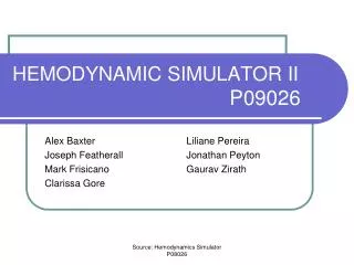
HEMODYNAMIC SIMULATOR
HEMODYNAMIC SIMULATOR. Rochester Institute of Technology. Cardiac Cycle. Project Background

HEMODYNAMIC SIMULATOR
E N D
Presentation Transcript
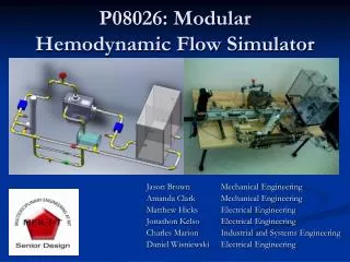
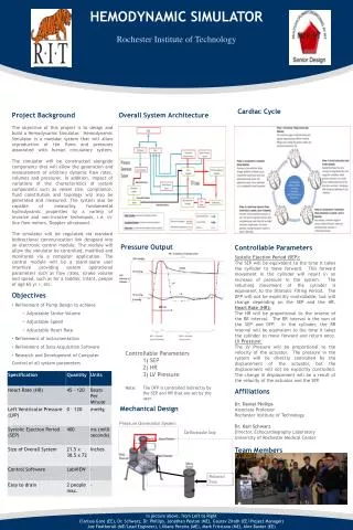
HEMODYNAMIC SIMULATOR Rochester Institute of Technology Cardiac Cycle • Project Background • The objective of this project is to design and build a Hemodynamic Simulator. Hemodynamic Simulator is a modular system that will allow reproduction of the flows and pressures associated with human circulatory system. The simulator will be constructed alongside components that will allow the generation and measurement of arbitrary dynamic flow rates, volumes and pressures. In addition, impact of variations of the characteristics of system components such as vessel size, compliance, fluid constitution and topology will also be generated and measured. The system also be capable of measuring fundamental hydrodynamic properties by a variety of invasive and non-invasive techniques, i.e. in-line flow meters, Doppler ultrasound. • The simulator will be regulated via standard bidirectional communication link designed into an electronic control module. The module will allow the simulator be controlled, modified and monitored via a computer application. The control module will be a stand-alone user interface providing system operational parameters such as flow rates, stroke volume and speed, such as for a toddler, infant, people of age 65 yr +, etc. • Objectives • Refinement of Pump Design to achieve • Adjustable Stroke Volume • Adjustable Speed • Adjustable Heart Rate • Refinement of instrumentation • Refinement of Data Acquisition Software • Research and Development of Computer Control of all system parameters • Specifications • Overall System Architecture • Pressure Output • Mechanical Design Controllable Parameters Systolic Ejection Period (SEP): The SEP will be equivalent to the time it takes the cylinder to move forward. This forward movement in the cylinder will result in an increase of pressure in the system. The returning movement of the cylinder is equivalent to the Diastolic Filling Period. The DFP will not be explicitly controllable, but will change depending on the SEP and the HR.Heart Rate (HR): The HR will be proportional to the inverse of the RR interval. The RR interval is the sum of the SEP and DFP. In the cylinder, the RR interval will be equivalent to the time it takes the cylinder to move forward and return once.LV Pressure: The LV Pressure will be proportional to the velocity of the actuator. The pressure in the system will be directly controlled by the displacement of the actuator, but the displacement will not be explicitly controlled. The change in displacement will be a result of the velocity of the actuator and the SEP. Affiliations Dr. Daniel Phillips Associate Professor Rochester Institute of Technology Dr. Karl Schwarz Director, Echocardiography Laboratory University of Rochester Medical Center Team Members Controllable Parameters 1) SEP 2) HR 3) LV Pressure Note: The DFP is controlled indirectly by the SEP and HR that are set by the user. Pressure Generation System Cardiovascular Loop Mechanical Pump In picture above, from Left to Right Clarissa Gore (EE), Dr. Schwarz, Dr. Phillips, Jonathan Peyton (ME), Gaurav Zirath (EE/Project Manager) Joe Featherall (ME/Lead Engineer), Lilliane Pereira (ME), Mark Frisicano (ME), Alex Baxter (EE)