Download
1 / 85
850 likes | 872 Views
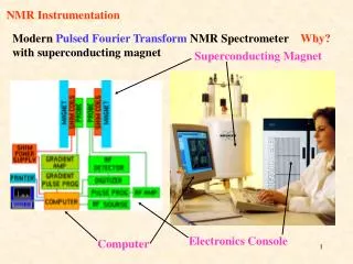
AMS Superconducting Magnet progress over the last 2½ months January 2007 Steve Harrison Scientific Magnetics. Magnet STA Magnet manufacture Valve qualification CGSE dewar update Helium vessel.

E N D
AMS Superconducting Magnet • progress over the last 2½ months • January 2007 • Steve HarrisonScientific Magnetics
Magnet STA • Magnet manufacture • Valve qualification • CGSE dewar update • Helium vessel
In October 2006 the CMR had been mounted in the STA vacuum vessel, and the 16 straps had been tensioned and adjusted.
The vacuum vessel weld fixture had been installed at Culham.
… to take signals from the accelerometers mounted on the cold mass replica …
The next task was to fit the temporary seals, but the sealing surface had been badly scratched.
With care, it was possible to make seals good enough for leak testing the small number of components which were not already tested.
Port cover Strap cover Turbomolecular pump Vacuum valve Mass spectrometer … for leak testing.
The assembly was leaktight, so the temporary seals were taken out from the bore.
The welding fixture now had to be dismantled to mount the STA.
… and transferred to the ring lifting beam for rotation and installation in the weld fixture.
After welding, and a prolonged weld examination process, the alodining was completed …
… and the STA was installed in the shipping fixture. It finally left Culham on 2 January 2007.
In October the magnet was mechanically complete, but had no cryogenic plumbing, and no electrical joints between the dipoles and racetrack coils.
Dipole heat shunt Racetrack heat shunt Cool down loop Conductor stabiliser Superfluid cooling loop Steel Cool down loop Copper
Inter-coil conductors have to be mechanically, thermally, and electrically stabilised over complicated geometries using ultra-high purity aluminium.
Conductor stabiliser Quench heater terminal The stabilisers have to be hand-crafted to fit the magnet geometry precisely. They are made from precision-bent, copper-plated aluminium.
Coil ends Unsupported length (max 30 mm) Copper plating allows the conductor to be soldered to the stabiliser.
The geometry of the flight cooling loops is not suitable for use in the test cryostat, so simplified loops are required.
Trial fit-up of one of the cooling loops for the magnet test.
Pure aluminium shunts for transferring heat from the coils to the cooling loops. All these components have to be tinned with solder.
Pre-tinning the cooling loop for connection to the heat shunts.
Re-fitting the cooling loop ready to solder up the heat shunts.
In October 2006, a test facility for acceptance testing (of up to 5 valves at a time) had been designed and manufacturing was just starting.