Summary of MICE Radiation Shield Installation and Initial Test Results (Collomb, 18th Oct 2012)
This summary details the installation and initial testing of the MICE Radiation Shield conducted by N. Collomb on October 18, 2012. It includes a comprehensive analysis of direct drive motor testing, metrology data, and adjustments made to ensure optimal performance. Key findings indicate that the direct drive design successfully passed proof of principle testing, demonstrating motion capabilities at an incline of 1.5° and secure holding at 2.5°. Outstanding actions such as manual handling assembly and cable routing are also highlighted for future attention.

Summary of MICE Radiation Shield Installation and Initial Test Results (Collomb, 18th Oct 2012)
E N D
Presentation Transcript
MICE Radiation Shield Installation Summary of initial test N. Collomb 18th October2012 1
MICE Radiation Shield Installation Table of Content: Direct Drive Test Metrology Data Analysis Summary Outstanding Actions N. Collomb 18th October2012 2
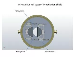
Direct Drive Motor Test Limits (Hard and electric) Direct Drive Motor strip Direct Drive Motor Bottom Rail Manual Handling key Lead shutters Radiation Shield Installation onto test bed back plate. 3
Direct Drive Motor Test Direct Drive Motor Direct Drive Motor strip On inspection found that the supplied lead frame components had been ‘flame – cut’. This caused the bracket, using the side as a datum, to ‘go out of square’ to the Linear Motion system. Doors were hard to open and close due to induced moments and forces. Lead frame – Linear Motion system interface issue Not all motor fingers engaged on drive strip due to “out of square” assembly. Rectified now. 4
Frames re-machined Direct Drive Motor Test All components re-assembled and squared with the result that the shield moves quite easily. Inclination of test plate measured. Rises on the right of image at an angle of 9 minutes. Motor able to drive shield extremely well. Limit switches not connected as the Joystick controller is only borrowed (plugs into AB1A controller box via 25 Pin D-Type) 42V PSU Joystick AB1A controller box Lead frame – Linear Motion system interface square. All motor fingers engage equally. 5
Limit switch at front Hard stop at back Direct Drive Motor Test N/O limit switch reading Limit switches and hard stops set to permit full closure and opening. Limit switch just closed 6
Direct Drive Motor Test Inclination of right hand side increased to 2°29’ Connected motor and attempted to drive shield ‘uphill’. Motor is NOT tracting sufficiently to move shield. Shield remained stationary and only a push caused it to slip. 7
Direct Drive Motor Test Inclination of right hand side increased to 2°29’ Note the difference in angle between the shield back plate and fence or stringers in back ground. Motor just moved shield sufficiently off the limit switch. The shield was driven to the right hand side and powered off. The position did not change over time (approx. 8 minutes) and a push was required to move the shield. Once the force was taken off the shield stopped. 8
Direct Drive Motor Test Inclination of right hand side reduced to 1°21’ At an inclination of 1°21’ the motor requires full power to move the shield to the end stop (‘uphill side’). The metrology data for the Spectrometer plate (e-mail R. Preece 10/09/2012) indicates that the holes are causing a rise/fall of 7.819mm over 1m (0.45°). Conclusion: The direct drive motor will comfortably move the radiation shield door up to an angle of 1 degree. The error in the Spectrometer plate is less than half of this figure and therefore the principle can be considered as proofed. 9
‘Nominal’ Spectrometer plate Metrology Data Analysis Coordinate systems represent Metrology data The datum for the metrology data and nominal spectrometer plate are coincident. 10
Metrology Data Analysis ‘Red Pin’ to represent metrology hole position relative to nominal Spectrometer hole position. Looking at top right hand corner of arrangement. Numerical analysis from data provided: ‘Red Pin’ to represent metrology hole position relative to nominal Spectrometer hole position. Looking at arrangement from RH side illustrates rise. 11
Top Bracket exhibits gap Metrology Data Analysis 1.64mm ‘Fitting’ the rail brackets to the metrology data highlighted a 1.64mm difference between the bottom and top holes. The plate is ‘leaning in’ at the top at an angle of 0.12733° . We can cater for this by elongating the interface plate holding the frame onto the bottom rails and/or the motor bracket at the top. Bottom Bracket Flush fitted onto plate 12
Metrology Data Analysis 6.64mm Adjusting the assembly, the previously misaligned holes can be aligned to within ±0.21mm The assembly does not require the manufacture of an adapter plate for the rail brackets as initially feared. The motors are able to move the shield at the incline (0.45°) and more importantly hold it in position (closed or open). 5.62mm 13
MICE Radiation Shield Installation Summary The Direct Drive design passed the proof of principle testing with ease. Motion is achieved up to an angle of 1.5° and holding is achieved at 2.5° quite easily. The misaligned spectrometer plate had caused concerns initially, indicating the need for an adapter plate between it and the rail brackets. Re-arranging the assembly slightly, opening/elongating of holes (in CAD) guarantees the shield to remain vertical. Sufficient allowance has been made to cater for this. 18th October2012 14
MICE Radiation Shield Installation • Outstanding Actions: • The Manual Handling arrangement needs to be assembled and tested. • The cable routing (inside Spectrometer) determined and finalised. • Some machining of components (enlarge and elongate holes) to cater for misalignment from metrology data. • Vacuum compatible rails to be ordered. • Wiring up to feed-through of electrical components. • Final testing (electrical and mechanical). • Determine location of AB1A Controller Box. 18th October2012 15
Radiation Shield µ-vie https://www.dropbox.com/s/s1qpq4j4ph4rmd8/MICE_Rad_Shield_Motion_12-09-28.mp4
Magnetic modelling A magnetic model was requested to establish the influence on the magnetic field and the forces generated on the system. The magnetic permeability was unknown for rail systems, thus a sample was analysed with a full B-H curve created by the National Physic Laboratory (NPL).
Magnetic modelling A CAD model was created showing the rail system relative to the solenoids and imported into OPERA 3D. Acknowledgement to M. Courthold and V. Bayliss
Magnetic modelling Top RH rail Results: The Top right hand rail experiences a force in the: X direction of 10N Y direction of -128N Z direction of -140N Whereas the bottom right hand rail the forces are: X = -7N Y = 183N Z = -171N The effect of the rails on the field produced by the coils is negligible – less than 3nT. The operation of the shield benefits from the “almost” cancellation of forces, bar in the Z – direction, hence no concerns mechanically. 140N 10N Y 183N 128N X 171N Z 7N Bottom RH rail Acknowledgement to B. Shepherd for his work.
Magnetic modelling conclusion Looking at the forces exerted by the magnetic field on the rail system the conclusion is that these are of no concern at a first estimate. The diminutive field distortion the components cause can also be considered negligible. There is still the need to change the rails for vacuum compatible units (current system only purchased due to long lead time).