Download
1 / 50
500 likes | 519 Views
Explore a paradigm for motion representation in perception space, covering Euclidean and projective transformations, epipolar geometry, motion recognition, and future prospects. Learn about projective motion, Euclidean space upgrade employing homogeneous coordinates, projective reconstruction from epipolar geometry, and projective camera concepts. Discover the significance of matching and tracking with two cameras, Lie group of projective motions, motion recognition via projective and rigid motions, and motion observation with camera pairs.

E N D
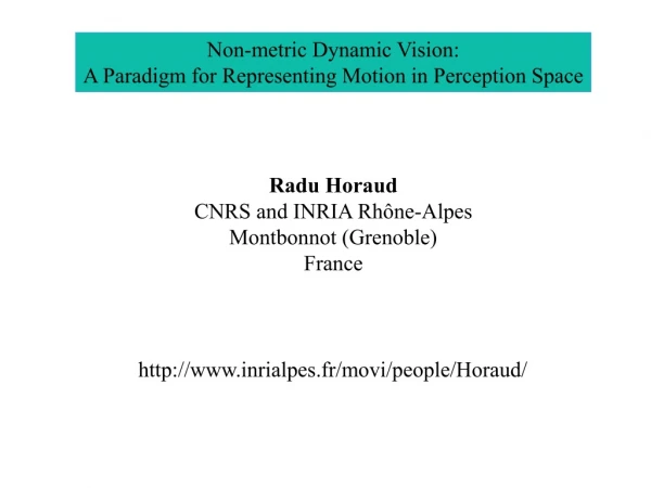
Non-metric Dynamic Vision: A Paradigm for Representing Motion in Perception Space Radu Horaud CNRS and INRIA Rhône-Alpes Montbonnot (Grenoble) France http://www.inrialpes.fr/movi/people/Horaud/
Acknowledgements • Gabriella Csurka, David Demirdjian, Andreas Ruf, • Frédérick Martin, Bart Lamiroy, Adrien Bartoli, • Peter Sturm, Tuan Luong, Bernard Espiau, Hervé Mathieu, • Sylvain Bougnoux, Roger Mohr, Long Quan, ... • European commission (various grants 1996-01 and beyond) • Sinters SA, Toulouse, France • Odense Steel Shipyard Ltd., Denmark • Aérospatiale, Paris
Motivation • Visual servoing or coordination of perception and action • Measure motion with calibration-free sensors • Representation of motion with a camera pair • The advantage of having two eyes from a geometric perspective
Outline of the talk • Euclidean representation of rigid motion • Brief introduction to projective space and transformations • The projective camera • One camera in motion • Two cameras in motion • Matching and tracking with two cameras • Projective representation of rigid motion • Projective representation of articulated motion • Visual servoing • Motion recognition • Future work
frame1 R, t frame 0 Rigid Motion 1 R - rotation t - translation
frame1 R, t frame0 Rigid Motion 2 M X0 = RX1 + t
M 3 x 1 translation vector 3 x 3 rotation matrix Rigid Motion 3 A physical point X0, X1... Euclidean representations of M (3-vectors) X0 = RX1 + t
same coordinates The plane at infinity A sphere of infinite radius has null curvature - a plane
Homogeneous coordinates Replace Regular point Point at infinity By:
4 x 4 matrix D At infinity as well At infinity Rigid motion and homogeneous coordinates X0 = RX1 + t
D Parallelism is preserved Rigid motion and parallelism Plane at infinity
Not at infinity ! Projective transformation Replace rigid motion D by H:
H Parallelism is not preserved Action of projective transformations Plane at infinity
projective coordinates of a physical point M Projective transformations define projective space 4 x 4 full rank matrix H
Hu HM = N upgrade X = Upgrading projective coordinates to Euclidean coordinates D = Hu H (Hu )-1 DHu = Hu H Euclidean space = DHu M Projective space
M m The projective camera m = P M 3-vector 4-vector P is a 3 x 4 projection matrix Center of projection
m One camera in motion
m m ’’ m’ m = epipolar line epipolar line m’TF m = 0 epipolar line m’’TF m ≠ 0 Epipolar geometry F
The fundamental matrix • F is a 3 x 3 homogeneous matrix of rank 2 • F maps a point onto a line • Introduced by Longuet-Higgins 1981 • Studied by Luong 1992 • May be computed from « scratch » using a • robust estimator (Zhang et al. 1995) • Allows projective reconstruction (Faugeras 1992, Hartley 1992)
Bad matches Epipolar geometry and mis-matching
M m m’ Projective reconstruction
Problems • Each time the camera moves, the epipolar geometry is • different and hence it must be estimated again and again • There are many cases (special motions, flat scenes) • for which the estimation above is ill-conditionned • The matching is still ambiguous • The projective to Euclidean upgrade is non-linear in nature • Numerical stability
No intersection! Ambiguous matching m
First epipolar geometry Second epipolar geometry Position 1 Position 2 Position 3 Self calibration
Columbia’s catadioptric stereo Stereo heads SRI small vision module
Two cameras in motion • Estimation of epipolar geometry becomes more tractable • Matching (left to right) and tracking (over time) • handled simultaneously • Projective to Euclidean upgrade has a linear solution • Representation of motion in « visual space »
Estimating the epipolar geometry Flat object Apparent 3-D object
Rigid motion Matching and tracking
Two cameras in motion Proj. rec. 1 Proj. rec. 2
H (projective motion) D (rigid motion) Rigid motion and projective motion Hu (upgrade) Proj. rec. 1 Proj. rec. 2 Hu (upgrade)
Lie group of projective motions H = (Hu )-1DHu • H is called projective motion • Projective motions form a sub-group of the projective group • It is a Lie group (isomorphic to the displacement group) • Projective velocity
Motion recognition D (rigid motion) and H (projective motion) have the same trace, same determinant, same eigenvalues with the same algebraic and geometric multiplicity
Motion recognition in practice • Observe motion with a camera pair; • Estimate projective motion from point-to-point matches; • Compute the singular value decomposition of H-I:
Identifying a rotation in projective space Matching, Proj. rec. Tracking, Proj. rec. Estimate H, etc.
4x4 matrix of rank 2 Parameterization of projective rotations
Other interesting features • 3-D reconstructin and sensor calibration at once • Motion segmentation • Representation of articulated motion • Robot calibration • Visual servoing of robots in projective space • Recognition of human actions
Conclusions • Motion representation that is consistent with stereo vision • Stereo-matching and tracking are treated consistently • Motion-based segmentation • It is an observer-centered representation • Articulated motion may be represented with the same scheme • Motion recognition • Identification of motion parameters • Hand-eye coordination with projective control