
Uploaded by
cera
5 SLIDES
329 VIEWS
50LIKES
三相交流调压电路实验
DESCRIPTION
VT1. 三相电源输出. R1. 电阻性负载. VT3. VT4. R2. VT6. VT5. U 1. V. A. R3. I 1. VT2. 三相交流调压电路实验. 一、实验目的. 1 、了解三相交流调压触发电路的工作原理。 2 、加深理解三相交流调压电路的工作原理。 3 、了解三相交流调压电路带不同负载时的工作特性。. 二、实验内容 1. 1 、观察并绘出锯齿波波形 2 、观察并绘出单、双输出脉冲波形 3 、观察并绘出 ā = 30 º 时负载端的波形
Download
1 / 5
Download Presentation 
三相交流调压电路实验
An Image/Link below is provided (as is) to download presentation
Download Policy: Content on the Website is provided to you AS IS for your information and personal use and may not be sold / licensed / shared on other websites without getting consent from its author.
Content is provided to you AS IS for your information and personal use only.
Download presentation by click this link.
While downloading, if for some reason you are not able to download a presentation, the publisher may have deleted the file from their server.
During download, if you can't get a presentation, the file might be deleted by the publisher.
E N D
Presentation Transcript
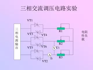
VT1 三相电源输出 R1 电阻性负载 VT3 VT4 R2 VT6 VT5 U1 V A R3 I1 VT2 三相交流调压电路实验
一、实验目的 • 1、了解三相交流调压触发电路的工作原理。 • 2、加深理解三相交流调压电路的工作原理。 • 3、了解三相交流调压电路带不同负载时的工作特性。
二、实验内容1 1、观察并绘出锯齿波波形 2、观察并绘出单、双输出脉冲波形 3、观察并绘出ā=30º时负载端的波形 4、调整给定电压观察并记录脉冲移相范围,记录Uct和α的值,绘制触发电路的传输特性α=f(Uct)曲线 ***波形绘在同一坐标系下***
实验内容2 用示波器观察α =30、60、90、120、150度时的输出电压波形,并记录相应的输出电压U的有效值于下表: 做出电路的移相特性Ud =f(α)曲线(Ud为负载电阻R上的电压有效值)
三、实验报告 • 1、整理并画出实验中记录的波形,作不同负载时的U=f(α)的曲线。 • 2、讨论、分析实验中出现的各种问题。
More Related