Download
1 / 25
260 likes | 505 Views
Advanced Accelerator Test Facilities at Daresbury Laboratory. Peter McIntosh (STFC Daresbury Laboratory) 2 nd PASI Workshop , RAL April 3 - 5, 2013. Overview. Daresbury Test Facilities: ALICE: SRF Cryomodule R&D RF Control – Microphonics and Lorenz Detuning EMMA NS-FFAG:

E N D
Advanced Accelerator Test Facilities at Daresbury Laboratory Peter McIntosh (STFC Daresbury Laboratory) 2nd PASI Workshop, RAL April 3 - 5, 2013
Overview • Daresbury Test Facilities: • ALICE: • SRF Cryomodule R&D • RF Control – Microphonics and Lorenz Detuning • EMMA NS-FFAG: • Beam Dynamics Studies • RF Control – Vector Sum Architecture • VELA: • Deflecting Cavity Diagnostics • Collaborative Opportunities • Conclusions
ALICE ERL Facility 8 MeV Compressor Photoinjector Laser IR-FEL Booster 35 MeV 8 MeV Acceleration • ALICE at Daresbury Laboratory operates using Energy Recovery principle. • Only accelerator of its type in Europe. • Used as an R&D test facility for next generation electron beam technology development. Linac Deceleration http://www.stfc.ac.uk/ASTeC/Programmes/Alice/35997.aspx
New SRF Cryomodule • Collaboration formulated in early 2006 to design and fabricate new CW cryomodule and validate with beam. • Dimensioned to fit on the ALICE ERL facility at Daresbury: • Same cryomodule footprint. • Same cryo/RF interconnects. • ‘Plug Compatible’ with existing cryomodule.
CM Component Testing Saclay-II tuner with wider aperture and low voltage piezocartridges, pinned and stress tested. Modified Cornell ERL injector coupler with a shortened cold section, high power conditioned. DESY superstructures (7Z2 & 7Z4) modified to incorporate optimised end groups. Cavities, cold couplers and central HOM absorbers installed. Cryomodule assembled & undergoing final cold testing.
DLLRF Implementation • LLRF4 • Designed at LBNL by L.Doolittle • Open source • Xilinx spartan3 FPGA • 4 -14 bit ADC Channels • 2 -14 bit DAC's • USB comms • Clock management chip • Cost ~$3k, built and tested • System installed in 2011 on NC buncher cavity. • To also install on SRF cavities: • 1.3 GHz. • High Q Superconducting Cavities. • 4ms pulse & CW • Fast feedback • Feed Forward for beam loading compensation.
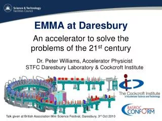
EMMA NS-FFAG EMMA is the only accelerator of its type in the world! http://www.stfc.ac.uk/ASTeC/Programmes/17426.aspx
Applications of NS-FFAGs • Proton & Carbon Therapy • Neutrino Factory High power proton driver • Accelerator driven reactor • Dedicated Muon Source
EMMA Objectives • Fixed energy operation to map closed orbits and tunes vs momentum • Many lattice configurations • Vary ratio of dipole to quadrupole fields • Vary frequency, amplitude and phase of RF cavities • Map longitudinal and transverse acceptances with probe beam from ALICE • EMMA is heavily instrumented with beam diagnostics
EMMA 6-Cell Girder Assembly F Magnet Location for diagnostics Cavity D Magnet Ion Pump Girder Beam direction
EMMA Ring Configuration Wall Current Monitor LLRF First user of Libera LLRF Located ~ 30 m from machine Septum Power Supply Kicker Power Supplies YAG Screen YAGScreen Septum Power Supply Kicker Power Supplies eBPM x 81
Realisation of EMMA August 2010 First Turn Second Turn 16th Aug 2010
Optimising RF for Acceleration • ToF zero crossing of each cavity to find optimum phase angle. • Beam loading effects could be seen on Libera system during phase optimisation. • Possibility to zero cross each cavity, tune for maximum acceleration. • Close Libera RF control loop to keep track of the correct phase of the system: • phase accumulator is reset during sweep. • LLRF control essential in order to achieve successful beam acceleration.
Successful acceleration in serpentine channel demonstrated. Published in Nature Physics (01/03/12) EMMA Acceleration Achievement Measured March 2011
VELA – Versatile Electron Linear Accelerator (ex EBTF) • For the development and testing of novel and compact accelerator technologies. • Through partnership with industry and the scientific community. • Aimed at addressing applications in medicine, health, security, energy, industrial processing and science. • Will enable research into areas of accelerator technologies which have the potential to revolutionise the cost, compactness and efficiency of such systems. • The main element of the infrastructure:- high performance and flexible electron beam injector facility feeding customised state-of-the-art testing enclosuresand associated support infrastructure. • Critical for development of underpinning technologies; • Advanced Beam Diagnostics, • Accelerating and Dipole Mode RF Structures, • RF Sources and Distribution Systems, • Vacuum Systems, • Magnet Systems, • Beam-based Feedback and Control Systems, • Beam Synchronisation Systems. VELA Pulsar
Accelerator Modules Module 4 Module 3 Module 5 Module 6 Module 1 Module 2 Module 1 http://www.stfc.ac.uk/ASTeC/Programmes/EBTF/38426.aspx
TDC Characterisation Estimated peak transverse voltage 5 MV (limited by available RF power) E-field H-field 3-cell TDC prototype (RI GmbH)
VELA Status and Layout Injector Room Enclosure 2 Control Room Rack Room First electrons by end April 2013 First beams for exploitation July 2013. Synchronisation Room Laser Room
Collaborative Opportunities • SRF Cryomodule Operation (ALICE): • CW SRF Cavity Operation: • Thermal Characterisation • Microphonics Assessment & feedback/forward Control • NS-FFAG Beam Dynamics (EMMA): • Serpentine Acceleration • RF Control Processes • Slow RF acceleration – Induction techniques? • Magnet Systems (Conventional & SC) • Deflecting/Crab Cavities (VELA/ALICE/EMMA): • Structure Designs • RF Control Developments • Vacuum Systems (VELA/ALICE/EMMA)
Conclusions • Innovative and unique accelerator test facilities available at Daresbury: • ALICE – Europe’s only ERL Facility • EMMA – World’s only NS-FFAG • VELA – High performance beam injector • Each allow for technology development and/or demonstration. • Although machines use electrons, compliance exists for proton technologies: • Accelerator Systems • RF Control/feedback/feed-forward/synchronisation • Deflecting/Crab Cavity Systems (Diagnostics/Beam Manipulation) • Magnets • Vacuum Systems • Opportunity to explore UK-FNAL collaboration in these (or other) areas.