Download
1 / 29
290 likes | 459 Views
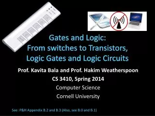
CS105 Introduction to Computer Concepts GATES and CIRCUITS. Instructor: Cuong (Charlie) Pham. Outline. Gates Types Construction Circuits Adder Multiplexer Memory IC. Computers and Electricity. Definitions: Gate: A device that performs a basic operation on electrical signals

E N D
CS105 Introduction to Computer ConceptsGATES and CIRCUITS Instructor: Cuong (Charlie) Pham
Outline • Gates • Types • Construction • Circuits • Adder • Multiplexer • Memory • IC CS105 Section 1 - Lecture 5
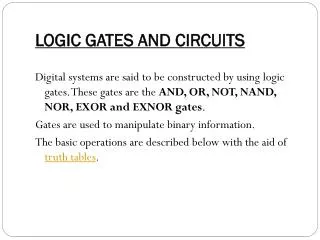
Computers and Electricity • Definitions: • Gate: A device that performs a basic operation on electrical signals • Circuits: Gates combined to perform more complicated tasks • How do we describe the behavior of gates and circuits? • Boolean expressions:Uses Boolean algebra, a mathematical notation for expressing two-valued logic • Logic diagrams: A graphical representation of a circuit; each gate has its own symbol • Truth tables: A table showing all possible input value and the associated output values CS105 Section 1 - Lecture 5
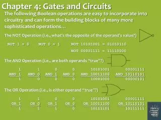
Gate Types • Six types of gates • NOT • AND • OR • XOR • NAND • NOR CS105 Section 1 - Lecture 5
NOT Gate A NOT gate accepts one input signal (0 or 1) and returns the opposite signal as output Figure 4.1 Various representations of a NOT gate CS105 Section 1 - Lecture 5
AND Gate An AND gate accepts two input signals If both are 1, the output is 1; otherwise, the output is 0 Figure 4.2 Various representations of an AND gate CS105 Section 1 - Lecture 5
OR Gate An ORgate accepts two input signals If both are 0, the output is 0; otherwise, the output is 1 Figure 4.3 Various representations of a OR gate CS105 Section 1 - Lecture 5
XOR Gate (exclusive OR) An XOR gate accepts two input signals If both are the same, the output is 0; otherwise, the output is 1 Figure 4.4 Various representations of an XOR gate CS105 Section 1 - Lecture 5
NAND Gate The NAND gate accepts two input signals If both are 1, the output is 0; otherwise, the output is 1 Figure 4.5 Various representations of a NAND gate CS105 Section 1 - Lecture 5
NOR Gate The NOR gate accepts two input signals If both are 0, the output is 1; otherwise, the output is0 Figure 4.6 Various representations of a NOR gate CS105 Section 1 - Lecture 5
Gates with More Inputs Gates can be designed to accept three or more input values A three-input AND gate, for example, produces an output of 1 only if all input values are 1 Figure 4.7 Various representations of a three-input AND gate CS105 Section 1 - Lecture 5
Constructing Gates Transistor • A device that acts either as a wire that conducts electricity or as a resistor that blocks the flow of electricity, depending on the voltage level of an input signal • A transistor has no moving parts, yet acts like a switch • It is made of a semiconductor material, which is neither a particularly good conductor of electricity nor a particularly good insulator CS105 Section 1 - Lecture 5
Constructing Gates • A transistor has three terminals • A source • A base • An emitter, typically connected to a ground wire • If the electrical signal is grounded, it is allowed to flow through an alternative route to the ground (literally) where it can do no harm Figure 4.8 The connections of a transistor CS105 Section 1 - Lecture 5
Constructing Gates The easiest gates to create are the NOT, NAND, and NOR gates Figure 4.9 Constructing gates using transistors CS105 Section 1 - Lecture 5
Circuits • Combinational circuit: The input values explicitly determine the output • Sequential circuit: The output is a function of the input values and the existing state of the circuit CS105 Section 1 - Lecture 5
Combinational Circuits Gates are combined into circuits by using the output of one gate as the input for another CS105 Section 1 - Lecture 5
Combinational Circuits Consider the following Boolean expression A(B + C) Does this truth table look familiar? Compare it with previous table CS105 Section 1 - Lecture 5
Combinational Circuits Circuit equivalence • Two circuits that produce the same output for identical input • Boolean algebra allows us to apply provable mathematical principles to help design circuits • E.g., A(B + C) = AB + BC (distributive law) so circuits must be equivalent CS105 Section 1 - Lecture 5
Adders • At the digital logic level, addition is performed in binary • Addition operations are carried out by special circuits called, appropriately, adders CS105 Section 1 - Lecture 5
Adders • The result of adding two binary digits could produce a carry value • Recall that 1 + 1 = 10 in base two Half adder • A circuit that computes the sum of two bits and produces the correct carry bit Truth table CS105 Section 1 - Lecture 5
Adders Full adder A circuit that takes the carry-in value into account Figure 4.10 A full adder CS105 Section 1 - Lecture 5
Multiplexers Multiplexer • A circuit that uses a few input control signals to determine which of several output data lines is routed to its output CS105 Section 1 - Lecture 5
Multiplexers • The control lines S0, S1, and S2 determine which of eight other input lines • (D0 … D7) are routed to the output (F) Figure 4.11 A block diagram of a multiplexer with three select control lines CS105 Section 1 - Lecture 5
Circuits as Memory • Digital circuits can be used to store information • These circuits form a sequential circuit, because the output of the circuit is also used as input to the circuit CS105 Section 1 - Lecture 5
Circuits as Memory • An S-R latch stores a single binary digit (1 or 0) • There are several ways an S-R latch circuit can be designed using various kinds of gates Figure 4.12 An S-R latch CS105 Section 1 - Lecture 5
Circuits as Memory The design of this circuit guarantees that the two outputs X and Y are always complements of each other The value of X at any point in time is considered to be the current state of the circuit Therefore, if X is 1, the circuit is storing a 1; if X is 0, the circuit is storing a 0 Figure 4.12 An S-R latch CS105 Section 1 - Lecture 5
Integrated Circuits Integrated circuit (also called a chip) • A piece of silicon on which multiple gates have been embedded • Silicon pieces are mounted on a plastic or ceramic package with pins along the edges that can be soldered onto circuit boards or inserted into appropriate sockets CS105 Section 1 - Lecture 5
Integrated Circuits • Integrated circuits (IC) are classified by the number of gates contained in them CS105 Section 1 - Lecture 5
Integrated Circuits Figure 4.13 An SSI chip contains independent NAND gates CS105 Section 1 - Lecture 5