Download
1 / 15
150 likes | 377 Views
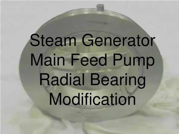
Steam Generator Main Feed Pump Radial Bearing Modification. Out-board Bearing. In-board Bearing. The CURRENT bearing temperature detector enters the bearing in the center, east side. Oil supply inlet. Original style bearing installed. Out-board bearing cover removed.

E N D
The CURRENT bearing temperature detector enters the bearing in the center, east side. Oil supply inlet Original style bearing installed. Out-board bearing cover removed
Bearing temperature detector enters the bearing in the center, right (west) side. Oil supply inlet In-board bearing cover removed
New StyleTilting PadRadial Bearings Notice that the bearings are DIRECTIONAL, and are installed in ONE direction of rotation. The new bearings have temperature detectors (RTD’s) installed INTO the bottom shoe.
RTD Lead With the new bearing installed in the correct rotational direction, the RTD leads will exit the bearing on the PUMP SIDE of the bearing and will exit the housing on the west side. Which is opposite of the original installation.
With the new bearing installed in the correct rotational direction, the RTD leads will exit the bearing on the COUPLING SIDE of the bearing. The RTD leads will go though the web of bearing saddle and will exit the housing on the west side.
Bearing RTD lead exits the in-board Bearing house on the west side. RDT lead where it exits the bearing on the coupling side, and goes through the bearing saddle.