Download
1 / 38
380 likes | 403 Views
This document outlines the upgrade plans for the XFT system at the University of Illinois and Ohio State University. It includes details on hit finding, segment finding, track finding, and the final linker system. The performance of the XFT in Run IIa has been excellent, with a momentum resolution of 1.74%/GeV/c and an efficiency of approximately 95%. The upgraded XFT system is expected to handle higher luminosity levels and maintain its excellent performance.

E N D
XFT Upgrade for Run II Mike Kasten, Suzanne Levine, Kevin Pitts, Greg Veramendi University of Illinois Richard Hughes, Kevin Lannon Ben Kilminster, Brian Winer Ohio State University October 13, 2003 DAQ Upgrade Review
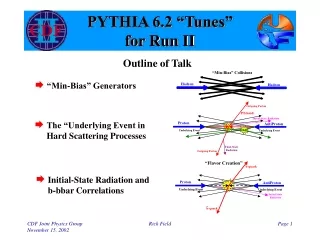
Outline of XFT Operation Good hit patterns are identified as segment, then segments are linked as tracks • Hit Finding: Mezzanine Card • Hits are classified as prompt or delayed • Segment Finding • In the axial layers, search for patterns of prompt/delayed hits consistent with High Pt tracks • Each segment found is assigned a pixel (phi, all layers) and possibly a slope (outer 2 axial layers only) • Track Finding • Looking across 3 or 4 axial layers, search for patterns of segments consistent with Pt>1.5 GeV/c • Resultant Pt and Phi of all 1.5 GeV/c tracks sent on to XTRP • Maximum of 288 tracks reported
XFT System • Mezzanine Cards • 168 cards • Classifies hits as prompt/delayed • Final Finder system • 24 SL1-3 boards • 24 SL2-4 boards • Heavy reliance on PLDs • Allows for some redesign: new patterns for number of misses, wire sag, faster gas, etc • Final Linker System • 24 Linker boards • Heavy reliance on PLDs • Allows for new road set based on new beam positions • Have already developed 2 new roads sets due to accelerator changes.
“Prompt” hit “Delayed” hit The Finder Track segments are found by comparing hit patterns in a given layer to a list of valid patterns or “masks”. Mask : A specific pattern of prompt and delayed hits on the 12 wires of an axial COT layer
Finder Output • In the inner two layers, each mask corresponds to 1 of 12 pixel positions in the middle of the layer. • The pixel represents the phi position of the track. • In the outer 2 layers, each mask corresponds to 1 of 6 pixel positions and 1 of 3 slopes: (low pt +, low pt -, high pt). • When a mask is located, the corresponding pixel is turned on.
Pixels must match Slopes must match The Linker Tracks are found by comparing fired pixels in all 4 layers to a list of valid pixel patterns or “roads”.
XFT Performance in RunII • Performance of the XFT in RunIIa has been excellent • Present and working for all runs • Momentum resolution 1.74%/GeV/c • Phi Resolution < 6mRad • Efficiency ~ 95%
XFT Run II Upgrade • The XFT was designed for a luminosity of: • L=1x1032cm-2s-1 396nsec bunch • <int/crossing> ~ 3 • L=2x1032cm-2s-1 132nsec bunch • <int/crossing> ~ 2 • Accelerator Performance • Max lum attained: 5x1031cm-2s-1 • Expect maximum of L=3x1032cm-2s-1 396nsec bunch • <int/crossing> ~ 9 • Factor of 3-4 above design
Extrapolated XFT Performance To determine the expected performance at high luminosity, we have focused on a number of different studies: • Monte Carlo overlaid with MBR min-bias; data overlaid with data minbias: • Allows us to check things like momentum and phi resolution, as well as fake fractions. • Problem: MBR min-bias seemed to underestimate occupancies • More sophisticated studies with min-bias (Kevin Lannon) • Compare data min-bias with MC min-bias (Pythia) • Overlay MC min-bias with various data samples to examine rates vs lum • Examining the fake rate in the two track trigger data sample as a function of instantaneous luminosity (Ben Kilminster) • Examining the electron trigger fake rate (and overall cross section) as a function of number of Z-vertices, then using this to extrapolate the cross section as a function of luminosity (Greg Veramendi)
Extrapolated Performance Phi and Pt resolution in 10 overlaid minbias (incele data + minbias data) A ttbar event with 10 overlaid minbias
Performance at High Luminosity Inclusive electron data overlapped with min-bias data Overlapping W+jets MC with MBR MC Note change in slope
Good Z vertices vs Lum number of good Z vertices as a function of bunch instantaneous luminosity (for run 167864 which has the 1.5Gev Pt 1&2 track trigs) compares total Z vertices per event with number of vertices with quality >= 12
Triggered Events Vs Lum Left plot: shows total number of events which pass the “scenario A” trigger • 2 xft tracks Pt > 2 GeV • sum(Pt) > 5.5 • dphi < 135 deg Right: same but unmatched tracks. Note: missing opp. charge requirement and 2 tracks per 15 deg hardware requirement)
Fake Trigger Fraction vs Luminosity Fake trigger fraction as a function of bunch instantaneous luminosity: • fake fraction extrapolates • 5% at 10E30 • ~35% at 100E30
Fake Fraction in Electron Triggers • Sample from dmon09 • Monitor Trigger: Auto-accept all L2 triggers at L3 • Filter: • L2_CEM16_PT8 • L2_PS50_L1_CEM8_PT8 • Auto-accept at L2 • L1 trigger (~11k events ): • 8 GeV XFT track + 8 Gev EM tower • L2 trigger (~63k events): • 8 GeV XFT track + 16 GeV EM cluster • Fake Fraction • Find all trigger track-cal. matches that satisfy trigger • Check if xft tracks have corresponding offline track • “Real” event: at least one track-cal match has corresponding offline track • “Fake” event: No corresponding offline track for any track-cal match • Nvert is measured using the ZVertCollection (4.8.4 did not have quality variable) L1 L2
<Nvert> Inst. Luminosity • Bunch luminosity allows probing larger instantaneous luminosity range • Measuring <Nvert> from data also takes into account ZVert efficiencies and fake rates
Trigger Cross Section Predictions Predictions for L1_CEM8_PT8 Predictions for L2_CEM16_PT8
Trigger Study Conclusions Trigger studies are very much a work in progress: • We do have data with >=5 z vertices, but not much. • The extrapolation to high luminosity/occupancy is very uncertain at this time • We really need to cross check with overlaid minimum bias to verify that the cross section does not suddenly turn up at some point • Unfortunately, many road blocks hindering this effort (merging COTD/Q; merging data vs MC, etc.) • The high Pt leptons are only part of the story • Need to consider track only triggers • Need to consider the effect of degraded XFT resolution on the SVT • We are making progress on this as well.
Improving The XFT • Degradation of XFT occurs in 3 areas: momentum resolution, phi resolution, and fake tracks • To improve things we need: • Better segment finding: This will reduce the number of spurious pixels reported to the Linker. • Axial Finders: improve phi and pt resolution. • Stereo Finders: Reject fake tracks • Better segment linking: Valid segments from different low pt tracks could be mistaken for a single high Pt track. This becomes a much bigger problem at high luminosity. Using better slope information at the linking stage reduces this problem.
Fake Tracks • The plots show the difference in slope between found XFT tracks and the nearest true Monte Carlo track. • The top plot is for “real” XFT tracks. • The bottom plot is for “fake” (unmatched) XFT tracks. • Conclusion: Fake tracks are due to combination of segments from differentreal tracks
Algorithm Changes • Hit Stage • Provide 6 times bins instead of the present 2 • Segment Finding Stage • Using 6 times bins, measure phi (pixel) position and slope at all 4 axial layers and 1 stereo layer. • Provide 5 slope bins at the outer two axial and outermost stereo layers, 3 slope bins at the inner two axial layers. • Segment Linking Stage • Require matching slope and pixel at all 4 axial layers, instead of limited (low pt) slope requirement at the outer two layers. • Require stereo confirmation for high Pt tracks, stereo association for all tracks.
Impact of Additional Timing Information • The additional resolution in timing at the hit level allows the Finder to measure the Pt or Slope of the segments with higfer precision. • We have added this new timing info to our full XFT simulation, to understand the impact on resolution at the segment finding level. • The top plot shows the improvement in slope resolution at the mask level. The solid curve uses the additional timing information. • The bottom plot shows the same for the slope resolution at the mask level.
Simulation of Upgraded XFT • Full simulation of RunII detector and occupancies necessary • Started on implementation of RunII XFT design using standard CDF environment • Preliminary indications of design performance Improvement expected from upgrade
Impact on Segment Linking • We have tested how better segment slope resolution can help reject fakes. • In a Monte Carlo sample, we smear segments found by the expected slope resolution. We then ask if this “measured” slope is above a high Pt threshold. • We require both segments from the outermost axial layer to have passed the high Pt threshold. • The upper plot is the efficiency for true tracks to pass the threshold. • The lower plot is the efficiency for fake tracks to pass the threshold.
Impact of Stereo • The stereo can have an impact in two ways: • Provide Z-pointing to tracks: Since EM and muon calorimeters are segmented in Z, coarse pointing can be very helpful in eliminating fakes • Confirmation Segment: Since often fake XFT tracks are the result of linking two unrelated low Pt segments, requiring another high Pt stereo segment in the allowed window around an axial track can be very powerful. • Note that the stereo has no impact on phi/pt resolution.
What changes:TDC to Finder • The upgraded TDC (?) replaces the current TDC + mezzanine card to provide hit information to the Finder. • However, the TDC transition cards, cabling, and Finder transition cards in the present system are reused. • Data is driven up the Ansley cables at the current clock of 22nsec. Two additional CDFCLK (@132nsec) are required to send up 6 time bins/wire versus the present 2 times bins/wire
What changes: Finder to Linker • The Finder control output, cabling, and Linker Input sections do not need to change. We use the additional 2 CDFCLKs (@132nsec) to transfer additional slope information. • The Linker output section can also remain the same as the present system. Algorithm chips need to be modified to handle increase in information.
Designing a New Linker Prototype Replace FPGA loading Retain VME control Retain clock control Retain input connectors and pinouts Retain VME connectors and pinouts Replace FPGA input (6) Replace FPGA output (2) Replace FPGA core algorithm (12)
Upgraded Finder Board • The input capture section runs at the same speed and does not change. • The pixel driver (output) section runs at the same speed and does not change. • The primary change is to the Finder pattern recognition chips. • Need more masks • Need to run faster since time is taken to input more data (3x more hit data) • New board layout needed since Finder chip footprint will change
Finder schematic “Finder chip” using Xilinx placeholder
Improving Pattern Recognition Chips • New Finder Chips • Expect factor of 7 more masks • Need to Run about factor of 2 faster (16nsec internal clock versus 33nsec internal clock) • New Linker Chips • Expect factor of 3.3 more roads • Need to run about factor of 2 faster(16nsec internal clock versus 33nsec internal clock)
The Stratix Chip • The original XFT design was done approximately 6 years ago, which is to say the PLD’s being used are outdated. • Technology has improved in the last 6 years. • Altera’s Quartus • To implement the new design we will be using Altera’s Quartus software in conjunction with their Stratix chip. • Full simulation of new Linker chips using latest Altera FPGA design software tools • Factor of >10 more logic elements • Factor of >100 more memory • Advanced I/O features • LVDS, SERDES • Factor of 4-6 faster
Using the New FPGAs • Current Linker chips use 7 year old technology: Altera EP10k50 devices. • Target device for upgraded design: Altera EP1S25 • First step: Implement current algroithm in new devices, with no changes • Design fits easily: factor of 10 less utilization; much faster (3-10x)
Implementing the Upgraded Linker Design • Key features: • Design uses much more slope information from the upgraded Finder design • 3 slopes inner two axial layers • 5 slopes outer two axial layers • Many more roads needed per 1.25 degrees: • Current: 1200 • Upgraded: 4000 • Design fully simulated using Altera software package (QUARTUS)
Installation Issues • Both the upgraded Finder and Linker boards will be designed to work in the current system as well as in the upgraded system • This should make testing the boards in the system much easier • As boards pass checkout, can replace current boards in the system • Testing the upgrade features can then be done with special runs, with little downtime for switching out boards • Can also “stage” the upgrade • Finders could be done first • Simulation work can tell us how much rejection we should expect from Finder alone, and from Finder plus Linker,
Progress over the past Year • Software: Have working XFT upgrade simulation • XTC, Finder,Linker upgrade algorithms are implemented • Working hard to quantify device degradation with luminosity • Linker Firmware: • Implemented old design in new STRATIX devices • Have compressed 12 chip 10K50 design into single EP1S25 device • Implemented upgraded Linker design (single chip) in EP1S25 device • Prototypes • Finder prototype schematic capture begun (sched: Jun 03) • Linker prototype schematic capture begun (sched: Jun 03) • “Firmware is everything!” • We are not changing input/output/cabling/transfer rate of the boards: primary changes are to the algorithm
Schedule • Can we make the production schedule? • Progress has been slow, but work has picked up dramatically with help from 3 new post-docs (all started ~Sep 03) • Linker production start date: Dec 2004 start, June 2005 finish • Finder production start date: Oct 2004 start, April 2005 finish • We are confident we can make this schedule • Do we want help? • YES! • Lots of work on simulation, test stand code, prototype checkout • If TDC is not upgraded, may also need to build new XTC’s (not in schedule at all)
Current work and Future Plans • Simulation work • Primary task over the next two months • Need to get merging code to work • Have a version of upgraded XFT simulation • This will guide what we need to build (Finder only, Finder + Linker, Stereo Finder, etc) • Hardware work • This proceeds in parallel with the simulation work • Algorithm development: • New Finder implementation in Altera (or Xilinx) • New Linker implementation in Altera • Will develop prototypes to gain experience with new devices as well as test the new algorithms • Hope to have Linker/Finder prototypes by early 2004