Download
1 / 11
110 likes | 296 Views
Mini Telescope USB (TAPIS) Beam Test DESY June 2007, CERN September 2007. W.Dulinski, G.Claus, M.Goffe. 4 plane M18 µTelescope: CERN Sept 07. Run 18520 – 18529. z position. 15. 10. ADC #. Chip #. S1: 2x2 mm. Beam. S2: 7x7 mm. t=700µm. Active. z. Mimosa18.

E N D
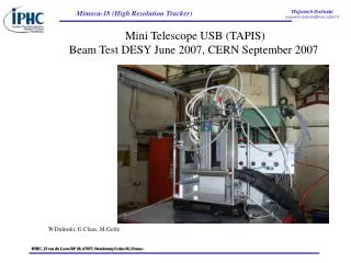
Mini Telescope USB (TAPIS) Beam Test DESY June 2007, CERN September 2007 W.Dulinski, G.Claus, M.Goffe
4 plane M18 µTelescope: CERN Sept 07 Run 18520 – 18529 z position 15 10 ADC # Chip # S1: 2x2 mm Beam S2: 7x7 mm t=700µm Active z
Mimosa18 • 512x512 pixel array (4 analog outputs) • 5x5 mm2 active area (7x7mm2 total) • 2T, self-bias architecture, standard diodes • 10 µm pitch • 16 (25) MHz readout clock 66 4 (3) ms integration • Excellent yield: 19 sensors bonded to PCB, on all of them >99.9% of pixels working correctly
Mimosa18 on PCB (from the chip side) Pixel(0,0) Pixel(0,0) A1 A2 Pixel(255,255) (for all arrays) A0 A3 Pixel(0,0) Pixel(0,0) ERNI connector (opposite side) cable
4-plane M18 µTelescope: CERN Sept 07 µTelescope 14/20 µm COOLING at 15°C *NO COOLING, BEAM and SCINT. POSITION ADJUSTMENT Mimosa 18 (carte USB nº26) Run effectue a 16 MHz τi = 4 ms Temperature liquide 15 º C
Mimosa17 (MimoTEL) • 256x256 pixel array (4 analog outputs) • 7.5x7.5 mm2 active area (8x9mm2 total) • 2T, self-bias architecture, rad-tol diodes • 30 µm pitch (STAR pixel design) • 16 (25) MHz readout clock 4 (3) ms integration • Yield: 15 sensors bonded to PCB (9 from 20 µm epi wafer 2006, 7 from 14 µm wafer 2006) • All OK, except two first 14 µm chips