Electrowetting
Electrowetting. Drop profile Wetting defects Wetting transitions. Marguerite Bienia , Catherine Quilliet, Marcel Vallade Laboratoire de Spectrométrie Physique Grenoble, France. From wetting. air. liquid. . . solid/liquid. solid/air. substrate. V. + + + + + + + + + + + +.

Electrowetting
E N D
Presentation Transcript
Electrowetting Drop profile Wetting defects Wetting transitions Marguerite Bienia, Catherine Quilliet, Marcel Vallade Laboratoire de Spectrométrie Physique Grenoble, France
From wetting... air liquid solid/liquid solid/air substrate
V + + + + + + + + + + + + - - - - - - - - - - - - - - - - - - - - …to electrowetting V Insulating solid Counter electrode Ew equation reduction of the contact angle of water on the insulator
An alternative geometry 2-fluid EW (brine/oil) : by matching densities, capillary length capillary forces dominate
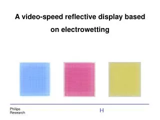
Examples of applications Hayes et al, Nature Sept 18 2003 Passive display device Blake et al, 2000 Coating assist Cho et al, 2002 splitting and merging of droplets Berge et al, 1999 Variable focus lens
Outline • Introduction • 1)Fundamental issue : • study of drop shape under electrical field 2)Electrowetting as an experimental solution for fundamental study of classical wetting : • wetting defects • wetting transitions
1. Drop ProfilesAbt.Angewandte Physik, Ulm, Pr Herminghaus, F. Mugele, EURODOC water on silanized 0.7mm glass V=1088V Total width : 1,3mm Problem : instability and drop expulsion what is the shape of the drop when an electrical field is applied?
Idea : electrostatic pressure compensated by an excess of capillary pressure V Pel electrode Pcap insulator V~
Numerical results Buehrle et al, 2003 interface profiles for increasing electrical field The range of the variation is proportional to e/R
Video camera V =7, e>200µm V and Video camera =7, e>200µm Direct measurements • EW on 150, 300,450µms glass coated with ~100A Teflon AF1600 • V range 1000-1500V • range 9550° • liquid : BMIM • EW on 160, 500µm teflon • V range 1000-1500V • range 100-50° • liquid : brine
Experiments 1.3mm Typical picture, 0V, vol=3.2µL symmetry plane
Curvature calculation Cylindrical symmetry r(z) Successive derivatives very noisy results!
Master curve C-C0 (µm-1) • Dots : experiment, =2 • solid line : theory Relative height
Perspectives • Profile extraction is impossible close to the triple line • very thick insulators needed • very high voltage required • Theoretical work still running
real case : a>r ideal case : 2. Hysteresis
Wetting defects • Joanny et al, 1984 : a model for contact angle hysteresis • Robbins et al, 1987 : hysteresis on random surfaces • Raphael et al, 1989 : single defect study • De Jonghe et al, 1995 : experimental physical and chemical defects on SiO matrix • Tanguy et al, 1998 : from individual to collective pinning: effect of long-range elastic interactions
Electrowetting defects Characteristic (and drawbacks!) of classical wetting defects : 1)wetting contrast is fixed! 2)defects are sometimes both chemical and physical Electrowetting may bring experimental solutions: 1)allow tunable wetting contrast for a given geometry of defects 2)no surface alteration, the defects are virtual study of a rectangular defect
_ _ _ _ _ _ _ _ _ _ + + + + insulator + + + + + + Principle of a bi-layered defect Wettability contrast
ground water oil PTFE 25 microns Vb glass 0.17mm Vd glass 1mm Experimental setup hydrophilic ring etched using Tetra-Etch (Gore) ITO, with an etched defect ITO (500Å =>transparent)
Results 25x30mm Reference electrowetting curve (increasing/decreasing voltage) obtained with a cancelled defect
Wetting contrasts • Wetting and non-wetting defects • left : experiment with an oil drop in water • right : simulations with Surface Evolver, for theoretical contact angles A : Vb=305V,Vd=400V b=107°, d=64° C : Vb=93V, Vd=696V b=45°, d=106° scale : 5mm
oil water system Sharp edge effect • Attraction between water and electrode • wetting is favoured along the edge of the defect insulator insulator
Conclusion • Feasibility of e-wetting defects is proved • Bienia et al, Langmuir • Wetting contrast is tunable, with • (De Jonghe, 1995 : =+71°) • Theoretical model : the precision of the defect is of the order of magnitude of the thickness of the insulating layer • Perspective : other defect geometries
3. Electrically induced wetting transitions • Motivation : • Induce wetting transitions through electrowetting • water in air or oil : partial to complete wetting impossible (EW saturation) • what kind of transition is possible?
water e oil insulator Effective interface potential effective interface potential P(e) : water-insulator interactions through oil • P(e) energy per unit surface • e=0 : • long range (a few nm): Hamaker constant A • ( for e) • short and intermediate range: no universal model
S Wetting regimes attraction repulsion P(e) P(e) P(e) e S e S eeq e S>0, A>0 pseudo-partial wetting S<0, partial wetting S>0, A<0 : complete wetting
water oil e, eeq insulator d,d electrode V Transition Effective potential without electrical field P(e) e resulting potential • Initial state : oil wets the insulator completely • By applying voltage : transition towards pseudo-partial wetting electrostatic energy Quilliet et al, 2002
System Brine and bromododecane on parylene, in the defect setup Hamaker constant : A=-6.2.10-21 J.m-2 <0, repulsive Same experiment on parylene+teflon AF1600
Ellipsometry multilayer ellipsometer made by Patrice Ballet Oil thickness after the transition : eeq<10nm for 20V
Setup ccd detector laser V ~ water 5mm ground oil gold 1000Å Parylene 2µm Silicon wafer Teflon cell
Multilayer ellipsometry on the detector Multilayer with thick and thin layers the water layer can be neglected air water (5mm) Multilayer system (oil + parylene) substrate
Ellipsometric parameters (,) : Preliminary results : Signal detection and treatment We consider the second spot :
Appendices Cross defect Profile extraction
Artefacts water on glass
Profile extraction (1) intensity profile on a line
Profile extraction (2) intensity
An example : cross defect V~ Idea : cross shaped electrode Increasing V