Download
1 / 22
220 likes | 337 Views
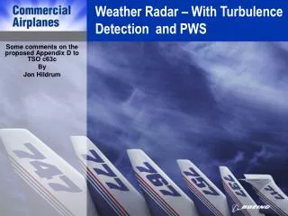
FY-05 Completion of the Minimum Performance Standard Airborne WXR with Turbulence Detection. Working Group Meeting NASA Langley May 24-26, 2005 Prepared by Kirk Baker, FAA. New. New.

E N D
FY-05 Completion of the Minimum Performance Standard Airborne WXR with Turbulence Detection Working Group Meeting NASA Langley May 24-26, 2005 Prepared by Kirk Baker, FAA
New New RTCA DO-220Minimum Operational Performance Standards For Airborne Weather Radar With Forward-Looking Windshear Capability. Dated 9/93 FAA SRD 10.2Interim Certification Requirements for Airborne Short and Long Range Windshear Prediction Systems (Forward Looking Windshear Systems) Dated 1/95 FAA Business Plan Current Design Standard Current Technical Standard Order RTCA DO-173Minimum Operational Performance Standards For Airborne Weather And Ground Mapping Pulsed Radar. Dated 11/80 FAA TSO C63cAirborne Weather And Ground Mapping Pulsed Radar Dated 8/83 • Does not include standard for windshear or turbulence detection FAA TSO C63dAirborne Weather And Ground Mapping Pulsed Radar Dated 8/83 • Development planned for completion by end FY-06 ATDS Working GroupMinimum Performance Standard (MPS For Airborne Weather And Ground Mapping Pulsed Radar with Turbulence Detection ATDS Working Group Part 25 Advisory Circular • Planned completion by end FY-08 • Both Standards are not currently recognized by FAA TSO C63c • Currently under development with planned completion by end FY-05 Proposed Design Standard
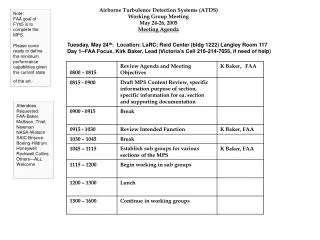
Meeting Goal’s By the end of this meeting: • Consensus on MPS Contents • Identified additional work • Establish due date for additional work in order to support • Establish date for last FY-05 meeting • Deliver completed MPS to AIR-100 with request for inclusion revision to TSO-63c
NASA/Industry Support • Propose an evaluation methodology for determining that the radar system detection calculations properly account for the various aircraft weight and wing load area characteristics across the transport fleet. • Propose a method of using the ADWRS for radar detection simulation. • Propose a set of turbulence models that provide for testing both the high (must detect) and low end (must not detect) of the wind field spectrum. • Propose a series of time evolutions for each turbulence model • Assist in the development of a set of aircraft flight scenarios for use in the laboratory simulation • Near and Far Range detections • Turbulence field tracking • Propose the methodology used for determining that the radar algorithms comply with the performance criteria set forth in the appendixes • Propose an methodology for evaluating probabilities for false and nuisance detection
MPS Draft Rev.- May 05 1.0 Purpose This Standard provides the Minimum Performance Standards (MPS) for Airborne Doppler Weather Radar with Forward-Looking Turbulence Detection and display capability.
MPS 2.0 Scope The scope of this appendix is to expand TSO c63d to include the MPS for an airborne Doppler weather radar system with forward looking turbulence detection and flight deck display. Some system designs may not include a dedicated radar display unit. They may instead share the display medium with other systems such as TCAS, NAV and TAWS. They may also share a multipurpose display such as an EFIS. For airborne radar systems with this architecture, the shared display device, when used for displaying of turbulence information, must meet the display requirements as set forth in this document.
2.1 Operational Goals The primary operational goal that can be satisfied by equipment meeting the performance standard set forth in this appendix will be to provide the flight crew with a situation display of severe convective turbulence ahead of the aircraft. This situation display is to be used as advisory information by the flight crew to make them aware of turbulence ahead of the aircraft. Together with other flight information, this turbulence information will be used in the decision making process for avoiding turbulence or in minimizing the effects of turbulence encounters.
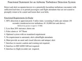
Req’s & Charac”s 3.0 General Requirements and Characteristics In addition to the performance requirements set forth in the main text of the TSO c63d, the following general requirements and equipment characteristics. 3.1 The radar receiver transmitter will detect and provide for the display of severe convective turbulence that would produce a peak load of >.3g’s to aircraft at a minimum of 30 seconds in front of the aircraft. (When should we inhibit the display of must detect?)
Req’s & Charac”s Some system designer may wish to provide detection and display of multiple levels of convective turbulence. For the levels that are established based on peak loads of less than .3g’s the designer must demonstrate through analysis, simulation and flight test that the methods used to display those areas are sufficiently distinct and do not distract from the minimum detection and display requirement of > .3g’s.
Req’s & Charac”s 3.2 The radar receiver transmitter shall not provide for the display of convective turbulence events that would produce a peak load of < . ? g’s. 3.3 To minimize the potential number of false display of turbulence caused by ground clutter, an automatic tilt control function shall be required when the radar antenna is operating in the turbulence scanning mode.
Req’s & Charac”s 3.4 Antenna stabilization errors shall be limited to ¼ degree, with no additional error at 20 – 40 degrees, when the antenna is operating in the turbulence scanning mode. 3.5 The maximum signal loss due to radome and waveguide shall be 4db. 3.6 The radar system shall use a Class C or better radome per DO-213. 3.7 The system performance must be satisfactory within the range of normal flight path angles.
Req’s & Charac”s 3.8 The probability of an un-annunciated failure in the radar receiver/transmitter shall be 10-4, or less, per flight hour of system operation. 3.9 The probability of dangerously miss-leading turbulence information generated by the radar receiver/transmitter shall be 10-4, or less, per flight hour of system operation. 3.10 The probability of false detections generated by the radar receiver/transmitter shall be 10-4, or less, per flight hour of system operation. 3.11 The radar receiver/transmitter shall provide for a pilot selectable on/off control.
4.0 Display 4.1 The radar receiver/transmitter shall provide output for the display of the severe convective turbulence fields using the color magenta. 4.2 The radar shall provide display of severe convective turbulence from at least 4000’ AGL up to the service limit altitude of the aircraft. 4.3 The minimum display range for a severe convective turbulence is 5nm. Will cover more on displays in the AC
Test 5.0 Test Requirements A combination of simulation and flight tests will be required to demonstrate compliance with Section 3.1 of this appendix. The applicant may choose to demonstrate compliance through other methods, than those described in this section, but will be required to provide justification through a formal deviation with the certifying authority.
Test 5.1 Turbulence Event and Aircraft Flight Scenario Models The following turbulence models shall be used to establish that the radar detection algorithm’s meet the minimum requirements set forth in Section 3.1 and 3.2 . They may also be used to test multi level detection algorithms design performance, which may require additional testing.
Test 5.1.2 Must Detect (> .3g’s) This model shall establish the RT’s ability to meet the minimum detection standard set forth in Section 3.1. Test scenarios should include runs against a model that provides for g loads just below and above the .3g event.
Test 5.1.3 Must not Display (<. ?g’s) This model shall establish the RT’s ability to meet the minimum detection standard set forth in Section 3.2. Test scenarios should include runs against the model that provides for g loads just below and above the .? g event.
Test 5.1.4 Turbulence Field Tracking and time evolution This set of models shall establish the RT’s ability to track and accurately predict the severe convective turbulence evolution over time.
Test 5.2 Radar and Aircraft Simulation This section shall provide the method’s for establishing that the simulation of the radar detection algorithm and target aircraft (s), meets the minimum detection standard set forth in Section 3.1 and 3.2. Specify the requirements for using the current version of ADWRS for radar simulation. Specify the requirements for aircraft simulation, taking in to account any dependencies by the detection algorithm to account for aircraft type.
Test 5.4 Comparative Analysis & Statistics This section shall provide the methodology for determining that the radar algorithms comply with the performance criteria set forth in the appendixes. It should include the methodologies for evaluating the receiver/transmitter probabilities for false and nuisance detection.
Test 5.5 Flight Test Evaluation and Analysis This section shall provide the methodology for verifying the simulation testing results. It shall also include testing for the dynamic aspects of the system operation that was not included as part of the simulation.
MISC Environmental Tests TSO C63c should be revised to address DO-178B Software Assurance and DO-254 Hardware Assurance) Any additional testing required for radar with ATDS? Area Scan(Is this the same for all of the functions?) Receiver Gain Control(Is this the same for all of the functions?) Frequency of Antenna Scan(Is this the same for all of the functions?) Bearing Accuracy (Is this the same for all of the functions?)