Download
1 / 58
630 likes | 1.09k Views
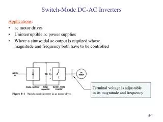
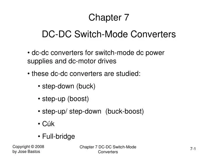
Chapter 7 DC-DC Switch-Mode Converters. dc-dc converters for switch-mode dc power supplies and dc-motor drives these dc-dc converters are studied: step-down (buck) step-up (boost) step-up/ step-down (buck-boost) Cúk Full-bridge. Block Diagram of DC-DC Converters.

E N D
Chapter 7 DC-DC Switch-Mode Converters • dc-dc converters for switch-mode dc power supplies and dc-motor drives • these dc-dc converters are studied: • step-down (buck) • step-up (boost) • step-up/ step-down (buck-boost) • Cúk • Full-bridge Chapter 7 DC-DC Switch-Mode Converters
Block Diagram of DC-DC Converters Chapter 7 DC-DC Switch-Mode Converters
Stepping Down a DC Voltage • switching at constant frequency: • pulse-width modulation (PWM) switching vo Chapter 7 DC-DC Switch-Mode Converters
Pulse-Width Modulation (1) • signal-level control voltage vcontrol generated by amplifying the difference between actual output voltage and desired output voltage • switch control signal generated by comparing vcontrol with repetitive waveform Chapter 7 DC-DC Switch-Mode Converters
Pulse-Width Modulation (2) • switch duty-cycle D is Chapter 7 DC-DC Switch-Mode Converters
Step-Down (Buck) DC-DC Converter (1) Chapter 7 DC-DC Switch-Mode Converters
Step-Down (Buck) DC-DC Converter (2) • average output voltage Vo Chapter 7 DC-DC Switch-Mode Converters
R L C low-pass filter Chapter 7 DC-DC Switch-Mode Converters
Continuous conduction mode (1) Chapter 7 DC-DC Switch-Mode Converters
Continuous conduction mode (2) Chapter 7 DC-DC Switch-Mode Converters
Continuous conduction mode (3) • input power equals output power: • step-down converter is equivalent to a dc transformer where the turns ratio is in the range 0-1 Chapter 7 DC-DC Switch-Mode Converters
Edge of Cont./Discont. Conduction • Critical current below which inductor current becomes discontinuous: Chapter 7 DC-DC Switch-Mode Converters
Discontinuous Conduction Mode Chapter 7 DC-DC Switch-Mode Converters
Discontinuous Conduction Mode (2) • Vo/Vd in the discontinuous mode • integrating the inductor voltage over one time period, • From the figure, Chapter 7 DC-DC Switch-Mode Converters
Discontinuous Conduction Mode (3) Chapter 7 DC-DC Switch-Mode Converters
Limits of Cont./Discont. Conduction with constant D • The duty-ratio of 0.5 has the highest value of the critical current • The boundary between the cont/discont mode is shown by the dashed curve Chapter 7 DC-DC Switch-Mode Converters
Discont. Conduction mode with constant Vo • in regulated dc power supplies Vo is kept constant by adjusting the duty ratio D • since Vd=Vo/D the average inductor current at the edge of cont/discont mode is • when D=0 the maximum ILB,maxis Chapter 7 DC-DC Switch-Mode Converters
Discont. Conduction mode with constant Vo Chapter 7 DC-DC Switch-Mode Converters
Step-Down Conv.: Output Voltage Ripple (1) Peak-peak voltage ripple: Chapter 7 DC-DC Switch-Mode Converters
Step-Down Conv.: Output Voltage Ripple (2) Computing : During toff: Chapter 7 DC-DC Switch-Mode Converters
Step-Down Conv.: Output Voltage Ripple (3) • ripple can be minimized by making fc of the low pass filter fc << fs Chapter 7 DC-DC Switch-Mode Converters
Step-Up (Boost) DC-DC Converter • Output voltage is greater than the input • main application: regulated dc power supplies Chapter 7 DC-DC Switch-Mode Converters
Step-Up DC-DC Converter Waveforms (1) Chapter 7 DC-DC Switch-Mode Converters
Effect of Parasitics • The duty-ratio is generally limited before the parasitic effects become significant Chapter 7 DC-DC Switch-Mode Converters
Step-Up DC-DC Converter Waveforms (2) • Assuming a lossless circuit Pd=Po • Thus: • power remains the same • voltage increases • current decreases • equivalent to a DC transformer Chapter 7 DC-DC Switch-Mode Converters
Edge of Cont./Discont. Conduction (1) Chapter 7 DC-DC Switch-Mode Converters
Edge of Cont./Discont. Conduction (2) • recognizing that the inductor current IL and the input current Id are the same Id= IL • and • highest ILB at D=0.5 • highest IOB at D=1/3 Chapter 7 DC-DC Switch-Mode Converters
Edge of Cont./Discont. Conduction (3) Chapter 7 DC-DC Switch-Mode Converters
Discont. Conduction (1) • Occurs at light loads Chapter 7 DC-DC Switch-Mode Converters
Discont. Conduction (2) Chapter 7 DC-DC Switch-Mode Converters
Discont. Conduction (3) Chapter 7 DC-DC Switch-Mode Converters
Discont. Conduction (4) Solving Io in order to 1 Substituting above Chapter 7 DC-DC Switch-Mode Converters
Edge of Cont./Discont. Conduction with Vd constant Chapter 7 DC-DC Switch-Mode Converters
Discont. Conduction with constant Vo (5) substituting IoB,max We get Chapter 7 DC-DC Switch-Mode Converters
Discont. Conduction with Vo constant (6) Solving for D Chapter 7 DC-DC Switch-Mode Converters
Boost Converter Output Ripple (1) Chapter 7 DC-DC Switch-Mode Converters
Boost Converter Output Ripple (2) • the ripple current flows through the capacitor and the average through R idiode Io (where =RC is the time const) Chapter 7 DC-DC Switch-Mode Converters
Step-Down/Up (Buck-Boost) Converter • The output voltage can be higher or lower than the input voltage • The output voltage is negative Chapter 7 DC-DC Switch-Mode Converters
Buck-Boost DC-DC Converter: Waveforms • equating the integral of inductor voltage over one period: • D>0.5 means Vo>Vd • D<0.5 means Vo<Vd • power is conserved Pd=Po: Chapter 7 DC-DC Switch-Mode Converters
Limits of Cont./Discont. Conduction (1) • The average inductor current is • Noting that average capacitor current is zero: re-arranging: Substituting: Chapter 7 DC-DC Switch-Mode Converters
Limits of Cont./Discont. Conduction (2) • Maximum values obtained when D=0 Chapter 7 DC-DC Switch-Mode Converters
Discontinuous Conduction Mode (1) • integrating the inductor voltage over one period • and since Pd=Po • This occurs at light loads Chapter 7 DC-DC Switch-Mode Converters
Discontinuous Conduction Mode (2) Chapter 7 DC-DC Switch-Mode Converters
Limits of Cont./Discont. Conduction ; Chapter 7 DC-DC Switch-Mode Converters
Limits of Cont./Discont. Conduction with Vo constant Chapter 7 DC-DC Switch-Mode Converters
Buck-Boost Converter: Effect of Parasitics • The duty-ratio is limited to avoid these parasitic effects from becoming significant Chapter 7 DC-DC Switch-Mode Converters
Buck-Boost Converter: Output Voltage Ripple (where =RC is the time const) Chapter 7 DC-DC Switch-Mode Converters
Cuk DC-DC Converter • The output voltage can be higher or lower than the input voltage • The output voltage is negative • Capacitor C1 stores and transfers energy • in steady state average inductor voltages VL1, VL2 are zero • VC1 is larger than Vd and Vo: Chapter 7 DC-DC Switch-Mode Converters
Cuk DC-DC Converter: Waveforms (1) • when switch T is off • VL1=Vd-VC1 • VL2=-Vo Chapter 7 DC-DC Switch-Mode Converters
Cuk DC-DC Converter: Waveforms (2) • when switch T is on • VL1=Vd • VL2=VC1-Vo Chapter 7 DC-DC Switch-Mode Converters