Download
1 / 12
150 likes | 315 Views
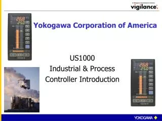
Yokogawa Corporation of America. US1000 Industrial & Process Controller Introduction. US1000 Digital Loop Controller. Large LED display Bar graph indications IP65 front panel Front panel or PC configuration Modbus communication option.

E N D
Yokogawa Corporation of America US1000 Industrial & Process Controller Introduction
US1000 Digital Loop Controller • Large LED display • Bar graph indications • IP65 front panel • Front panel or PC configuration • Modbus communication option • Single or dual loop PID control • Loop power supply for two-wire transmitters • Universal inputs & outputs • Up to 7 contact inputs/outputs
US1000 Features • T/C, RTD, mV or VDC input(s) • Relay, voltage pulse or DC current output(s) • Up to 7 DI / DO (3 relays) • Up to 14 different control strategies • 24VDC power supply for transmitter(s) • Custom computation capability • US1000-11 or -12 • FM & CSA for Div. 2 areas
Agency Approvals • Factory Mutual • Class 1, Div. 2, Gps. A,B,C,D • Available since December, 1999 • Canadian Standards Association • Class 1, Div. 2, Gps. A,B,C,D • CE Mark • Installation in Europe
M3.5 screw terminals Screw for 149mm Depth Terminal cover Terminal Cover is one of the standard accessories. Rear Size & Wiring Terminals Overall Dimensions: 72 x 144 x 150 mm 8.83 x 5.67 x 5.91 in Panel Cutout: 68 x 137 mm 2.68 x 5.39 in
PV Display First Digit: Hierarchy of the Parameter Second to Fifth Digit: Parameter Name SV Display: Parameter Data PV, SV & MV Bar Graph displays are active during Parameter Setting. Setup Parameters Access • 11 segment PV/Parameter display. • Hierarchy of parameter shown. • To access SETUP • menus, US1000 must be in MANUAL
Auto-tuning ends at 3rd peak. Being Auto-tuning SV PV PID control according to PID parameter obtained by auto-tuning. 100% 100% MV 0% Auto Tune Feature • Uses open loop response to calculate PID values. • Automatically varies the output (MV) from 0-100% to determine step response. • Auto tune is turned off after the third PV peak. • Super control (fuzzy logic) is available for control stability during PV disturbances or setpoint (SV) changes.
PC or PLC MODBUS or PC-Link Max: 1200m Up to 31 controllers Option /A10 for PC or PLC Communication • MODBUS RTU or ASCII (RS485 2 or 4 wire) • Up to 31 controllers per serial port. • Distance is limited to 1200 m (4000 ft). • Can be connected to Lantronix LDS-10 for network connectivity. (Modbus TCP)
Custom Computation • Available in US1000-11 & -21. • Requires LL1200-E10 Custom Computation Tool. • Select a US mode similar to the application requirements. • Select the appropriate computational modules. • Download the custom computation using the light loader or RS485 comm. port.
Analog Inputs Contact Inputs Module Module Module Custom Computation Module Module Control Functions Ctrl1 Ctrl2 Custom Computation Module Module Module Module Module Current or Pulse Output Contact Outputs Custom Computation Block Diagram • Computation is accomplished by linking modules. • Math modules (+, -, *, /, absolute value, reciprocal, etc.) • Logic modules (AND, OR, XOR, NOT, <, >, counter, etc.) • Special modules (SUM, time, linearizer, totalizer, etc.)
AIN3 AIN1 AIN2 DI2 DI3 DI4 DI5 DI6 DI7 DI1 Custom Computation Example Double click on computational modules to assign functions. Assign any parameters required for the function block. Links are automatically shown after assigning input and output links. A1 0 Differential Pressure Input Temperature Compensation Pressure Compensation Square Root Extraction 0 41: EUCONV 1 A2 400 2730 62: TCOMP 1 2 0 0 C3 A3 103 100 15:OR 63: PCOMP 2 4 3 A4 10 73: SQR1 5 1 0 20000 A5 10000 C5 0 74: FLWSUM 19:GT TRK1 CSV2 PVIN1 PVIN2 TRF1 MAN1 AUT1 MAN2 AUT2 R/S SV1 CSV1 0 6 7 O/C GAIN2 FF TRK2 TRF2 CAS1 CAS2 DP1 DP2 MSG1 GAIN1 PV Input to the PID Control Function Block Custom Computation Example