Download
1 / 32
330 likes | 477 Views
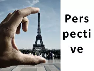
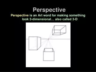
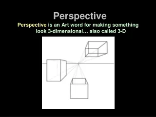
2D Techniques to Represent 3D. Perspective. Perspective – Brief History. Perspective is a technique used to represent three-dimensional images on a two-dimensional picture plane . Developed and formalized into the methods we still use today by two 15th century architects

E N D
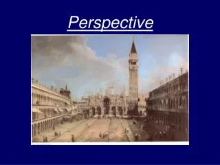
2D Techniques to Represent 3D Perspective
Perspective – Brief History • Perspective is a technique used to represent three-dimensional images on a two-dimensional picture plane. • Developed and formalized into the methods we still use today by two 15th century architects • Leon BaptistaAlberti(1404-72) • Filippo Brunelleschi (1377-1446).
Point of View • For 500 years, perspective drawing remained one of the basic principles of Western art until it was challenged by the ideas of the Cubists at the start of the 20th century Cubist Landscape by Baciamille
Classical Perspective • According to Leonardo da Vinci, there are three aspects of perspective • The size of objects should seem to diminish (become smaller) according to distance • Colors should change (become weaker/paler) the farther away they are from the eye • Objects should be drawn or painted less carefully (less finished) the farther away they are
Using Perspective • Two main elements in perspective drawing: • Linear Perspective which deals with the organization of shapes in space. • Aerial Perspective which deals with the atmospheric effects on tones and colors. • Also called Atmospheric Perspective
Linear & Aerial Perspectives The image on the left is an example of Linear Perspective. It shows some of the lines are used to arrange & align the shapes of blocks and columns to create an illusion of depth and distance. The image on the right displays the atmospheric effects of Aerial Perspective. You can see how the tones weaken and the colors pale as they recede from view.
The Picture & Ground Planes • The Picture Plane is the flat two-dimensional surface on which we draw or project an image in perspective. • In this illustration, it is simple to draw the two rectangles as long as they are parallel to the picture plane. • The Ground Plane is at 90 degrees to the picture plane. • In this illustration, the ground plane is the grey surface on which the shapes appear to be standing. It starts at the bottom of the picture plane, stretches back to the horizon and is emphasized by the shadows which are cast upon it.
Non-Parallel Planes • When an object is at an angle to the picture plane, it is more difficult to render its shape. This is where the rules of perspective drawing come into play. • In this illustration, the rectangles are seen at an angle of 90 degrees to the picture plane as they recede along the ground plane. This creates an illusion of depth. Their shapes are no longer identical and have changed according to the rules of perspective.
The Horizon/Eye Level • The horizon/eye level is the horizontal axis around which a perspective drawing is constructed. • Outdoors, the horizon is used as a point of reference to judge the scale and distance of objects in relation to the viewer. • In perspective drawing, the horizon also happens to be the viewer's eye-level. • The term, 'eye level', is often used rather than 'horizon' because the horizon may be hidden by walls, buildings, trees, hills etc.
Location of the Horizon • The location of the eye level/horizon line in a composition will have a profound effect as the image automatically becomes an extension of the viewer’s personal space. • Since the horizon is also the viewer’s eye level, he can more easily understand the scale and space of the image in relation to his own body • This effect works whether objects are small or large, near or far, or whether the viewer is standing, sitting or lying down.
Mid-level Horizon Line • A neutral eye level helps create an equal balance between the sky and foreground in a landscape • It gives the impression that the viewer is witnessing a scene from the same level as the characters in the picture
High Horizon Line • A high eye level in perspective drawing focuses more attention on the middle and distant areas of a composition • The viewer has a restricted view of objects that are close because she is essentially looking down on them. • A high horizon line is not appropriate for all compositions . • A high eye level is the ideal arrangement for panoramic landscapes.
Low Horizon Line • Creates the space for a large area of sky, which becomes a major influence on the scale, tone, color and mood of the composition. • A low eye level can be used for dramatic effects by: • SCALE - emphasizes the height and power of objects in the foreground. Makes the viewer feel small. • TONE and COLOR - the sky is the key light source in a landscape and sets the tone and color of the composition (dark or light)
Consistent Eye Level • In this perspective drawing, note how all four figures share the same eye level - i.e. the horizon of the picture. • This suggests that they are all the same height and are standing on the same plane. • Because the horizon happens to be at the viewer’s eye level, it also suggests that the figures are the same height as any viewer of the picture. • The organization of scale and distance in the drawing makes good visual sense.
Inconsistent Eye Level • In this drawing, although the figures are still the same size, their eye levels no longer have any relationship to the eye level of the picture. As a result, the scale of the figures is totally confused. • This demonstrates the importance of the horizon / eye level to the organization of scale and distance in a perspective drawing.
Basic Elements of Perspective • There are three basic elements used in perspective drawing: • HORIZON (implied at intersection of BLACK & GRAY) • ORTHOGONAL LINES (shown in RED) • TRANSVERSAL LINES (shown in GREEN) • VANISHING POINTS (shown in BLUE)
Orthogonal Lines • Parallel to the ground plane and move back from the picture plane. • Set the varying heights or widths of a shape as it recedes from view. • Always appear to meet at a vanishing point on the eye level.
Transversal Lines • Always at right angles to the orthogonal lines. • Parallel to the picture plane and to one another. • Establish a fixed height or width between two orthogonal lines. • Form the nearest and furthest edges of a shape as it recedes from view.
Vanishing Points • Dots at eye-level where parallel lines seem to converge (come together) and disappear • This illustration uses a single vanishing point and demonstrates the simplest form of perspective drawing: One Point Perspective.
One Point Perspective • Uses a single vanishing. Simplest form of perspective drawing • Front and back transversal planes of a shape remain parallel to the picture plane. Only their scale changes as they recede into the distance • Receding orthogonal lines change their angles to converge at vanishing point
Two Point Perspective • Uses 2 sets of orthogonal lines and 2 vanishing points to draw each object. • Has no planes that are parallel to the picture plane • Vertical transversal lines are still drawn parallel to one another and at right angles to the ground plane.
“Invisible” Vanishing Point • The second vanishing point may be situated outside the frame of the picture • If both vanishing points are situated within the picture frame, the angles of objects appear to be extremely foreshortened.
Three Point Perspective • Most complex form of perspective drawing • Uses three sets of orthogonal lines and three vanishing points to draw each object • Used when drawing objects viewed from a low or high eye-level • Low eye level creates the illusion that a shape is towering above the viewer. It naturally suggests the scale of a tall building.
Tilted Picture Plane • In one and two point perspective, the picture plane is fixed at right angles to the ground plane. In three point perspective, the picture plane seems to be set at an angle as the viewer tends to tilt their head back or forward to look up or down from the eye level. • Vertical transversal lines, which are parallel in 1 and 2 point perspective, appear to recede, forming a third set of orthogonal lines, which rise from the ground plane and eventually meet at vanishing point 3, high above the picture plane.
3 Point – High Eye Level • Three point perspective is also used when drawing an object from a high eye level, creating the illusion of looking down from a high viewpoint. • This drawing process is simply a reversal of the method used for drawing a box from a low eye level (high horizon vs. low horizon)
Perspective Circles • A circle in perspective is called an ellipse • Circular perspective is drawn the same as rectangular perspective • There are two distinct stages in its creation: • fig.1. The circle is first visualized in plan form on a flat square grid . Each section of the grid contains one quarter of the circle. • fig.2. The square grid is distorted according to the laws of perspective. The circle is then redrawn onto the distorted grid to create an ellipse • In the illustrations, the diagonals of the grid have been drawn on to help with the plotting of the circle and ellipse
Cylindrical Perspective • A cylinder is simply a circle which is projected into three dimensions. • Fig. 1 is an illustration of a cylinder which is formed by a circle being projected vertically from the ground plane. • The ellipses that outline the cylinder are all the same width. • The roundness of their curves gradually increases as they rise above or drop below eye level. • Note how the ellipse at the eye level is seen as a straight line.
Cylindrical cont. • Fig .2. This is an illustration of a cylinder which is formed by a circle being projected horizontally from the picture plane. • The circular curves that form the cylinder are all the same shape, but their scale reduces as they recede from the picture plane towards the vanishing point.