Download
1 / 50
550 likes | 1.13k Views
Learn about the importance of piston weight in engine balancing and how to choose the right pistons for your engine. Understand the impact of piston weight on rod bearings and engine performance. Helpful tips and cautions for selecting replacement pistons. Real-world fix for piston pin issues and cylinder wall scoring.

E N D
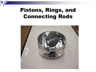
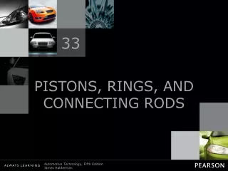
33 PISTONS, RINGS, AND CONNECTING RODS
Figure 33-1 The piston seals the bottom of the combustion chamber and is attached to a connecting rod.
Figure 33-3 A piston diameter is measured across the thrust surfaces.
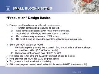
TECH TIP: Piston Weight Is Important! All pistons in an engine should weigh the same to help ensure a balanced engine. Piston weight becomes a factor when changing pistons. Most aluminum pistons range in weight from 10 to 30 ounces (280 to 850 grams) (1 oz 28.35 g). A typical paper clip weighs 1 g. If the cylinder has been bored, larger replacement pistons are obviously required. If the replacement pistons weigh more, this puts additional inertia loads on the rod bearings. Therefore, to help prevent rod bearing failure on an overhauled engine, the replacement pistons should not weigh more than the original pistons. CAUTION: Some less expensive replacement cast pistons or high-performance forged pistons are much heavier than the stock pistons, even in the stock bore size. This means that the crankshaft may need heavy metal added to the counterweights of the crankshaft for the engine to be balanced. For the same reason, if one piston is being replaced, all pistons should be replaced or at least checked and corrected to ensure the same weight.
Figure 33-4 A cast piston showing the sprues which were used to fill the mold with molten aluminum alloy.
Figure 33-5 The top of the piston temperature can be 100°F (38°C) lower on a forged piston compared to a cast piston.
Figure 33-6 Valve reliefs are used to provide valve clearance.
Figure 33-7 Piston cam shape. The largest diameter is across the thrust surfaces and perpendicular to the piston pin (labeled A).
Figure 33-8 A moly graphite coating on this piston from a General Motors 3800 V-6 engine helps to prevent piston scuffing.
Figure 33-9 The head of the piston is smaller in diameter than the skirt of the piston to allow it to expand when the engine is running.
Figure 33-10 Steel struts cast inside the piston help control expansion and add strength to the piston pin area.
Figure 33-11 Most piston pins are hollow to reduce weight and have a straight bore. Some pins have a tapered bore to reinforce the pin.
Figure 33-12 Piston pin offset toward the major thrust surface.
Figure 33-13 Engine rotation and rod angle during the power stroke cause the piston to press harder against one side of the cylinder, called the major thrust surface.
FREQUENTLY ASKED QUESTION: Which Side Is the Major Thrust Side? The thrust side is the side the rod points to when the piston is on the power stroke. Any V-block engine (V-6 or V-8) that rotates clockwise is viewed from the front of the engine. The left bank piston thrust side faces the inside (center) of the engine. The right bank piston thrust side faces the outside of the block. This rule, called the left-hand rule, states the following: • Stand at the rear of the engine and point toward the front of the engine. • Raise your thumb straight up, indicating the top of the engine. • Point your other fingers toward the right. This represents the major thrust side of the piston. Always assemble the connecting rods onto the rods so that the notch or “F” on the piston is pointing toward the front of the engine and the oil squirt hole on the connecting rod is pointing toward the major thrust side with your left hand.
Figure 33-14 Circlips hold full-floating piston pins in place.
Figure 33-16 The rings conduct heat from the piston to the cylinder wall.
REAL WORLD FIX: Big Problem, No Noise Sometimes the piston pin can “walk” off the center of the piston and score the cylinder wall. This scoring is often not noticed because this type of wear does not create noise. Because the piston pin is below the piston rings, little combustion pressure is lost past the rings until the groove worn by the piston pin has worn the piston rings. Troubleshooting the exact cause of the increased oil consumption is difficult because the damage done to the oil control rings by the groove usually affects only one cylinder. Often, compression tests indicate good compression because of the cylinder seals, especially at the top. More than one technician has been surprised to see the cylinder gouged by a piston pin when the cylinder head has been removed for service. In such a case, the cost of the engine repair immediately increases far beyond that of normal cylinder head service.
Figure 33-17 Combustion chamber pressure forces the ring against the cylinder wall and the bottom of the ring groove to effectively seal the cylinder.
Figure 33-18 The side and back clearances must be correct for the compression rings to seal properly.
Figure 33-19 This typical three-piece oil control ring uses a hump-type stainless steel spacer-expander. The expander separates the two steel rails and presses them against the cylinder wall.
Figure 33-21 The taper face ring provides oil control by scraping the cylinder wall. This style of ring must be installed right side up or the ring will not seal and oil will be drawn into the combustion chamber.
Figure 33-22 Torsional twist rings provide better compression sealing and oil control than regular taper rings.
Figure 33-23 Scraper-type rings provide improved oil control.
Figure 33-24 The upper barrel face ring has a line showing contact with the cylinder wall. The second taper face ring shows contact along the lower edge of the ring.
Figure 33-25 The chrome facing on this compression ring is about 0.004 in. (0.10 mm) thick.
Figure 33-26 The moly facing on this compression ring is about 0.005 in. (0.13 mm) thick.
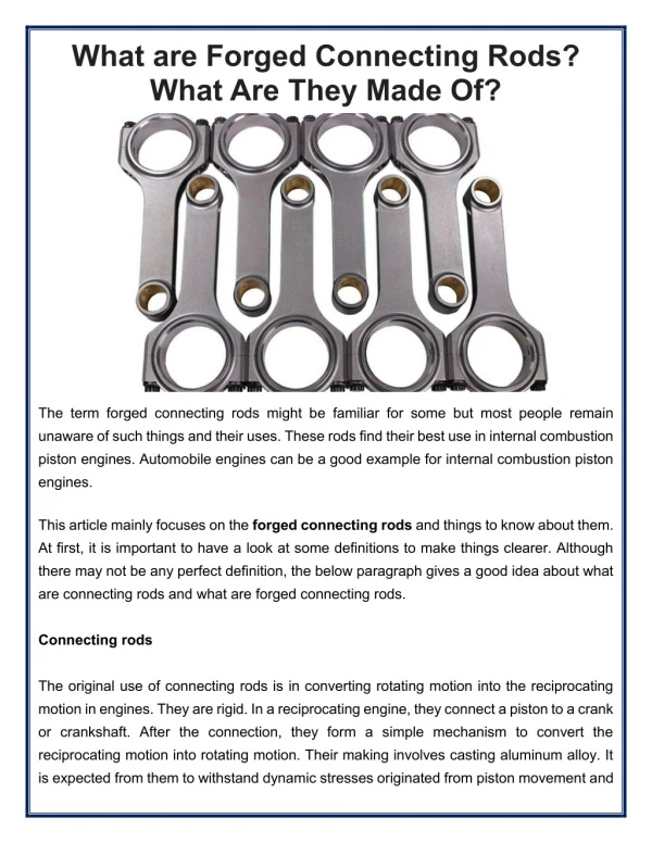
Figure 33-27 The connecting rod is the most highly stressed part of any engine because combustion pressure tries to compress it and piston inertia tries to pull it apart.
Figure 33-28 The I-beam shape (top rod) is the most common, but the H-beam shape is common in high-performance and racing engine applications.
Figure 33-30 Some rods have balancing pads on each end of the connecting rod.
Figure 33-31 Some connecting rods have spit holes to help lubricate the cylinder wall or piston pin.
Figure 33-32 Some engines, such as this Ford diesel, are equipped with oil squirters that spray or stream oil toward the underneath side of the piston head to cool the piston.
Figure 33-33 A cast connecting rod is found on many stock engines and can be identified by the thin parting line.
Figure 33-34 This high-performance connecting rod uses a bronze bushing in the small end of the rod and oil hole to allow oil to reach the full-floating piston pin.
Figure 33-35 Powdered metal connecting rods feature a fractured parting line at the big end of the rod.
Figure 33-36 A press used to remove the connecting rod from the piston.
Figure 33-37 If the rod is twisted, it will cause diagonal-type wear on the piston skirt.
Figure 33-38 A rod alignment fixture is used to check a connecting rod for bends or twists.
Figure 33-39 Rod bearing bores normally stretch from top to bottom, with most wear concentrated on the rod cap.
Figure 33-40 To help ensure that the big ends are honed straight, many experts recommend placing two rods together when performing the honing operation.
Figure 33-41 The small end of the rod is being heated in an electric heater and the piston is positioned properly so the piston pin can be installed as soon as the rod is removed from the heater.
Figure 33-42 The side clearance of the piston ring is checked with a feeler gauge.
Figure 33-44 A hand-operated piston ring end gap grinder being used to increase the end gap of a piston ring so that it is within factory specifications.
Figure 33-45 A typical ring expander being used to install a piston ring on a piston.
Figure 33-46 Identification marks used to indicate the side of the piston ring to be placed toward the head of the piston.