Download
1 / 33
330 likes | 348 Views
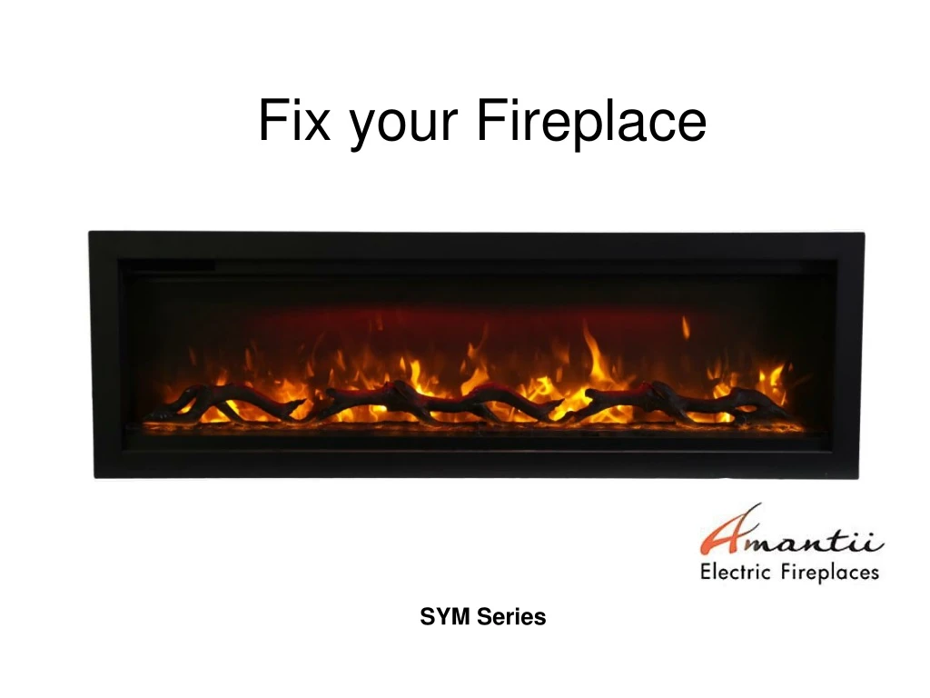
Learn how to replace LED lights, flicker motor, heating element, PCB board, signal receiver, and canopy light in your SYM Series Fireplace. Ensure safety by turning off power before attempting any replacements.

E N D
Fix your Fireplace SYM Series
SAFETY FIRST TO AVOID ANY ELECTRICAL SHOCK OR POTENTIAL DAMAGE TO THE UNIT REMEMBER TO TURN THE POWER OFF TO THE UNIT BEFORE ATTEMPTING TO REMOVE OR INSTALL ANY PARTS.
Content • How to replace LED light • How to replace flicker motor • How to replace heating element • How to replace the PCB board • How to replace the signal receiver • How to replace the canopy light
Replace LED light Replace ember bed LED light Step 1 Remove Trim - remove the screws circled in red so the trim can be removed. Screws will be needed to reinstall the trim.
Magnetic stone Trim Please note that there are magnetic stones on the bottom of the trim that attaches the trim to the bottom face.
Step 2 After the trim has been removed, the front glass panel can be removed. Front glass panel
Step 3 Remove steel side panels. The steel side panels hold the log in place. Remove the 4 screws circled in red to remove the side panels. Screws will be reused to reattach the steel side panels. The steel panels
Step 4 The log can now be removed from the unit once the side panels are out. Remove the log be lifting one end of the log upwards as seen in the picture below.
Step 5 After the steel panels have been removed, the ember bed glass panel can carefully be removed by rising one end up first and then out. The ember bed LED strips are located below it. Remember this is a piece of glass and can break if not handled with care.
Step 6 The LED strips are held in place with screws and are connected to the other strips or to the end using a molex connector. Unscrew the screws of the failed LED strip and unplug the molex connector to replace it with a new one. Unscrew Unplug
Replace Flame LED light Follow STEP 1 to 5 in Replace Ember Bed LED light, you come to here. Step 1 Remove the screws circled in red to remove the steel bar fixing the back glass to the unit. Remove steel bar from unit. Glass can now be removed from the unit.
Step 2 Remove flame effect steel panel. To remove the panel, remove the 2 screws shown circled in red on each side of the unit. Remove the panel and set aside. Zoomed View Zoomed View
After the flame effect steel panel has been removed, you come to here. Horizontal view LED strips for flame effect lie here Bird’s eye view
HOOK MOLEX CONNECTOR Step 3 Remove flame effect steel panel. To remove the panel, remove the 2 screws shown circled in red on each side of the unit. Remove the panel and set aside.
Replace flicker motor Follow STEP 1 to 5 in Replace Ember Bed LED light, you come to here. Step 1 Remove the back glass to expose location of the Flicker motor. Unscrew the screws circled in red to remove the steel bar that secures the back glass. Remove steal bar and set aside. The back glass can now be removed and set aside. .
Step 2 Remove flame effect steel panel. To remove the panel, remove the 2 screws shown circled in red on each side of the unit. Remove the panel and set aside. Zoomed View Zoomed View
After the flame effect steel panel’s been removed, you can see the flame motor on the left end.
Steps to remove Flicker Motor Step 1 Step 2 Step 3 The motor is connected using spade connectors. Carefully disconnect the motor and replace Unscrew the clamp that secures the flicker rod onto the motor. Remove the rod by carefully pulling it off of the motor Unscrew the 2 screws circled in red to remove the motor from the fireplace.
Replace the heating element Follow STEP 1 to 4 in Replace Ember Bed LED light. Step 1 Remove the back glass to expose the flame effect steel panel. Unscrew the screws circled in red to remove the steel bar that secures the back glass. Remove steal bar and set aside. The back glass can now be removed and set aside.
Step 2 Remove flame effect steel panel. To remove the panel, remove the 2 screws shown circled in red on each side of the unit. Remove the panel and set aside. Zoomed View Zoomed View
Step 3 Unscrew the screws circled in red
Step 4 Remove inner top panel. Remove the screws circled in red to take off the inner top panel. The heating element, PCB board, Canopy light and Signal receiver are all fixed on it.
HEATING ELEMENT INNER TOP PANEL
Step 5 Unscrew the screws circled in red to take off heating element assembly from the inner top panel.
Step 5 To replace the element, remove the screws circled in red that secures the heating element assembly from to the inner top panel and carefully remove the heater.
Step 6 Remove heater brackets from the heater by removing the screws circled in red. Unplug the heater and replace it with a new heater. NOTE: When removing the heater, take note of how it was removed. The rubber spacers need reinstalled the same way that they were removed
Replace the PCB board Follow STEP 1 to 4 in Replace the heating element. PCB board INNER TOP PANEL
Step 1 Remove the 4 screws circled in red and replace the failed PCB board with a new one. Secure the new board to the inner top using the same 4 screws used to remove the board
Replace the signal receiver Follow STEP 1 to 4 in Replace the heating element to take off the inner top panel. The signal receiver lies here Step 1 Remove the 2 screws circled in red to take the signal receiver off the inner top panel.
Step 2 The receiver is connected to the PCB board using a molex connector. Follow the lead from the receiver back to the board and disconnect it from the PCB board. A new receiver can be connected to the PCB board then secured to the inner top of unit.
Replace the Canopy light Follow STEP 1 to 4 in Replace the heating element to take off the inner top panel. The canopy light assembly
Step 1 Remove the screws circled in red to disconnect the canopy light assembly from the inner top panel.
Step 2 Picture 1 Picture 2 Unplug the canopy light from molex connector that is attached to the PCB board. Gently pull it out as shows in picture 2. A new Canopy light can now be installed.