Download
1 / 49
490 likes | 629 Views
Systems Analysis II OO Design use case realizations. INFO 355 Glenn Booker. Use case realization. Use case realization is based on developing detailed design for your system to implement one complex use case of interest This is done via interaction diagrams

E N D
Systems Analysis IIOO Design use case realizations INFO 355 Glenn Booker Week #5
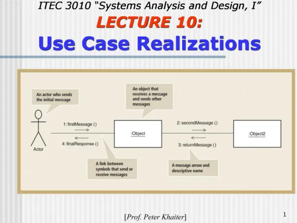
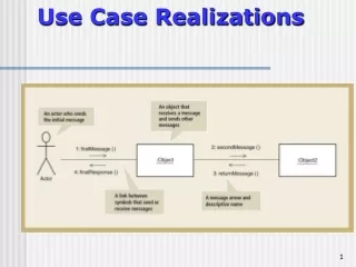
Use case realization • Use case realization is based on developing detailed design for your system to implement one complex use case of interest • This is done via interaction diagrams • Here we focus on a sequence or communication diagram to develop interaction between actor and system Week #5
Use case realization • As use cases are defined in detail, the classes and methods defined feed back into the design class diagram • Recall we had three major types of classes – interface, control, and data • A controller class is often used to manage performing one use case Week #5
Class names • Class names should use a suffix to identify their type clearly • Interface classes might end with Form, Screen, Window, or Menu • Controller classes end with Controller or Handler • Data classes end with Data Week #5
Interaction Diagrams • Interaction diagrams include • Sequence diagrams • Collaboration (in UMLv1)(or communication, UMLv2) diagrams • Either type describes ONE USE CASE • Unlike the class diagram, which pertains to the whole system Week #4
Interaction Diagrams • Interaction diagrams describe how one or more actors interact with the system to perform a use case • The development of interaction diagrams motivates the development of methods (i.e. making them up), which later become part of the design class diagram Week #4
Making up Methods??? • Yes, as part of object oriented design, you need to specify the methods which will be associated with each class • Method names start with a verb • Such as: get, set, create, calculate, display, obtain, append, delete, etc. • And end with the noun (often the type of data or object involved) Week #4
Getters and Setters • Two of the most common methods are to read the value of a variable (get), or assign the value of a variable (set) • getQuantity would read the value of some field Quantity • setQuantity would assign or set the value of Quantity, ignoring its previous value (if any) Week #4
Returns from the System • In response to messages, the system often provides some sort of data in return • This can be explicitly shown by a dashed line • The line is labeled with the type of data provided by the system, such as totalPrice or discountedValue • Returns generally point to an interface object, so an actor can see the data Week #4
Returns from the System • Return messages often fulfill a system response identified in the use case description (hint!!!) • If the use case states ‘system displays the total amount due’, then some return message will probably need to contain totalAmountDue (or something like that) Week #4
Method versus Message • We often use ‘method’ and ‘message’ interchangeably • A method is code which belongs to some object • A message is the command to execute a method Week #4
Identifying Objects • Interaction diagrams can identify specific objects (not just classes) • Name objects and classes using the formatobject:Class • For example, employee:Person means there is an object “employee” of the Class “Person” Week #4
Identifying Objects • Notice the Class name is capitalized, but the object name is all lower case, and the phrase is underlined • If you don’t need to specify the object name, just use the format :Class • Note the leading colon and underline Week #4
Identifying Actors • Sequence diagrams do not have to show the primary actor explicitly • Earlier UML (versions 1.x) showed the primary actor in the form of the stick figure we saw in the use case diagram • Often, the first message in an interaction diagram is a direct result of some action by the primary actor Week #4
System Sequence Diagram • The System Sequence Diagram, mentioned in my UML summary and in the text, will not be covered here to avoid confusion Week #4
Sequence Diagram Week #5
Sequence Diagram • A sequence diagram shows the messages needed to perform a use case, in chronological order • Time is assumed to advance as you move down the page (top to bottom) • Steps in a sequence diagram often (not always) correspond to the steps in a scenario for that use case Week #4
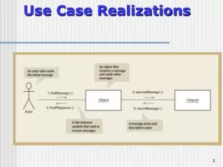
Generic Sequence Diagram Clearly these are not meaningful class or method names. No returns are shown. Notice that messages may go right-left as well as left-right Week #4
Notation for Sequence Diagram • Each class or object is identified in a box, with a dashed line extending below it • When an object is in use, a narrow rectangle can be added over the dashed line • This rectangle is an activation bar; it shows the lifespan of that object Week #4
Sequence Diagram … Sequence • The sequence of actors and objects from left to right on a sequence diagram is generally the order in which they are used • Typically this results in the primary actor on the far left, then an interface object, etc. Week #4
Where to begin? • To develop an interaction diagram, use the use case documentation to • Identify the primary actor • Use the MVC (or interface, control, and data objects) pattern to make up the objects which will be used to follow the main success scenario • Label messages appropriately to read, move, and analyze data as needed Week #4
Where to begin? • Consider also the ProductSpecification pattern • A common result is for an artifact to start with a document, such as an invoice, which has • Line entries for each thing on that invoice, and • Draws information about each line from a ProductSpecification class Week #4
Where to begin? • Where significant, add return messages only to describe important information obtained as a result of the messages Week #4
Self-called Messages • An object may call its own methods • The message line makes a U turn to the line from which it started, and is still labeled with the method name Week #4
Object Creation and Deletion • A special notation is used for the creation of an object during a use case • The message points to the new object, and the message is labeled ‘new’ or ‘create’ • When an object is no longer needed, it is deleted (slide 19) • Message is labeled ‘close’ or ‘delete’ Week #4
Decisions, Decisions • Conditional statements (If) are shown in brackets [x<10] or before a colon leading to the message Week #4
Loops! • Loops (repeat activity until some condition is met) are shown on a sequence diagram by placing a box around the set of repeated messages • The looping condition is in brackets • [for each line item] • [input data is not valid] Week #4
Note: UML v2 calls them ‘communication’ diagrams, but ‘collaboration’ is still used in Visio and the current UML standard Collaboration (or Communication) Diagram Week #5
Collaboration Diagram • A Collaboration Diagram looks like a class diagram, since it has boxes (with class or object names) connected by lines • But here, the lines correspond to message paths, not associations • It shows what messages are passed between objects Week #4
Collaboration Diagram • To show the chronological order of messages, a collaboration diagram MUST NUMBER MESSAGES • The first object dictates the start of each numbering series • Its first message is number “1.”, the second “2.”, etc. • Messages which follow as a result of the first message get 0.1 added for each message, i.e. 1.1, 1.2, 1.3, etc. Week #4
Collaboration Diagram • Then the messages which follow message “2.” do likewise, 2.1, 2.2, 2.3, etc. • This establishes threads of messages • Some people just number the messages sequentially (1, 2, 3, …), but this is not compliant with any UML standard Week #4
Collaboration Diagram • The other critical thing is to determine where messages ‘live’ (what object is responsible for implementing them): • The object to which a message points (its target) is responsible for implementing that message • This also applies for sequence diagrams Week #4
Generic Collaboration Diagram This matches the sequence diagram on slide 18 Week #4
Collaboration Diagram • Notice that lines between classes have no arrowheads, but each message is labeled with an arrow • The next slide shows the implied class characteristics from this case • Notice that the ability to pass messages implies association between classes Week #4
Class Diagram for slide 18 Same case shown in slide 18Attributes, labels and multiplicity not shown Week #4
Package diagram Week #5
Packages • Classes are the most basic logical element in an OO system • We need a way to group related classes into larger structures • A Package can contain classes, other packages, or a combination of the two Week #6
Packages • Packages can therefore have a large scope (e.g. entire subsystems) • In writing, a double colon separates a package name from its contents • Package::otherpackage::classname Week #6
Package Diagram • The Package Diagram can be very helpful in understanding the architecture of a system • What are the big pieces of this system? • Defining connections among packages also helps encourage higher modularity for each package Week #6
Packages • In a diagram, a package may be just a tabbed folder • Or a package can list its contents (classes and/or packages) (this was done manually in Visio) Week #6
Packages • The smallest packages can be drawn large enough to include the class diagram they contain (also done manually) Week #6
Packages • If showing a class diagram within a package, can show connection to other packages by using the fully qualified name of the class in another package • See also the <<system>> stereotype Week #6
Package Diagram • Packages can contain both packages and classes • Dashed lines show direction of dependency Week #6
Package Dependencies • For additional refinement, dependencies can be labeled with various stereotypes, such as • Call • Instance • Copy • Derived • Send • Import Week #6
Package Generalization • Generalization can be shown with packages, not just classes • Might be used in implementation to distinguish among different kinds of similar interfaces, for example Week #6
Packages • It is possible to have classes with identical names in different packages • Customer::Person • Client::Person • You might want this to reuse non-primitive data type classes Week #6
Package Stereotypes • Packages can specify stereotypes to indicate their purpose • <<façade>> to indicate the façade pattern is being implemented with this package • <<system>> to indicate the package represents an external system Week #6
Package Stereotypes • <<stub>> could represent a package which isn’t going to be implemented yet, but is a placeholder • <<framework>> represents a commercial development framework Week #6
Package Visibility • Packages can have the same visibility characteristics as any class, method, or attribute • Public • Private • Protected • This doesn’t show on its symbol Week #6