Download

1 / 66
660 likes | 806 Views
Passive Optical Networks in Particle Physics Experiments. 24 th November, PH-ESE Seminar. Work conducted by PH-ESE-BE-OPTO Team Members. Outline. Commercial PON technologies PONs in Timing Systems for HEP Future PONs and their implications in Timing Systems. Commercial PON technologies.

E N D
Passive Optical Networks in Particle Physics Experiments 24th November, PH-ESE Seminar Work conducted by PH-ESE-BE-OPTO Team Members 24/11/2009
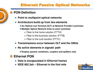
Outline • Commercial PON technologies • PONs in Timing Systems for HEP • Future PONs and their implications in Timing Systems 24/11/2009
Commercial PON technologies • PON definition • Motivation for current work • PON Protocols • PON Transceivers • Optical Components 24/11/2009
PONs in Access Networks Access Network Backbone Network Metropolitan Network • Access Networks are the last segment connection from COs (central offices) to customers • They are also called first-last mile networks • Examples of access networks are: • ISDN • xDSL • WiMAX • and most recently PONs… DSLAM POTS CO xDSL ISDN Ethernet, SONET etc WDM mesh PON OLT CO WiMAX
What is a PON? • PON is a Point-to-MultiPoint (PMP) optical network with no active elements in the signal’s path from the source to the destination • Data are exchanged between a central node, the Optical Line Terminal (OLT), and a number of end terminals, the Optical Network Units (ONUs) • A long feeder fiber delivers the data close to the ONUs before signal is split by means of an optical splitter and secondary fibers • According to where ONUs are placed we have different PON versions namely FTTH, FFTC, FFTB etc FTTH FTTC FTTB
General PON Considerations • In the downstream direction (OLT→ONUs) PON is a broadcast network • ONUs are filtering out data not addressed to them • In the upstream direction (ONUs→OLT) however a number of customers share the same transmission medium and some channel arbitration mechanism should exist to avoid collisions and to distribute bandwidth fairly among ONUs • TDM is the preferred multiplexing scheme in first generation PONs as it is very cost effective. Dynamic Bandwidth Allocation Algorithms are employed for fairness. All intelingence is built in the OLTs • Upstream transmission is of burst mode type FTTC FTTB
Motivation • There are currently P2P and P2MP optical links in LHC • P2P links are used in DAQ due to high bandwidth demands • P2MP links are used to transmit timing information • Current TTC system is unidirectional (optically) • A slow electrical feedback is used to communicate the status of the subdetectors back to the TCS • It would be beneficial to replace this electrical link with a higher bit rate, “real” time optical link 24/11/2009
System Requirements • System has to be able to deliver synchronous triggers and commands continuously • Latency has to be fixed at both transmitting and receiving ends • Recovered clocks have to be of low jitter • System must provide with the flexibility of both individually addressing or broadcasting to slave nodes • Slaves have to be able to respond in short time 24/11/2009
TDMA PON Protocols • Ethernet PON (E-PON) established by IEEE. Work started in 2001, completed in 2005. IEEE 802.3-2005 • Supports Ethernet frames • Giga-bit PON (GPON) established by ITU. Work started in 2001 completed in 2004. ITU G.984 • Supports mixed ATM and Ethernet frames through generic encapsulation method (ITU G.7041) • >95% of LAN data are of Ethernet type but the battle is still on…
GPON and EPON Frames Downstream EPON MSB GPON SLD + LLID MSB sequence used for the sync of the ONU Rx PCBd Indicates start of frame Counter indicating larger frames (superframes) 125 μs, 19440 bytes for 1.244 Gb/s Management – Control commands Length or type of Ethernet frames mutually exclusive Bit interleaved parity Specifies length of BW map and ATM partition Payload / Pad 46 – 1500 Octets Start time – Stop time for N < 4096 different AllocIDs Payload GEM header ONU 1 Data ONU 1 … Downstream ONU 1 OLT ONU N GEM header ONU N Data ONU N FCS (4 octets) LSB Error correction
Bandwidth Allocation Schemes ONU 1 • BW allocation schemes are not part of protocols • However, both EPONs and GPONs provide with the necessary information for any allocation algorithm to be implemented • Two main bw allocation schemes: • Fixed/Static Bandwidth Allocation (FBA) • Dynamic Bandwidth Allocation (DBA) 1 2 3 1 2 3 6 8 1 2 3 6 7 4 5 6 7 4 5 1 2 3 4 5 4 5 FBA PON ONU 2 OLT … Upstream ONU N ONU 1 DBA PON 7 ONU 2 6 7 8 OLT … Upstream ONU N
PON Transceivers • Burst mode laser drivers at Slave (ONU) • FP lasers and PIN diodes for cost efficiency • Burst mode RXs at OLTs • APDs for high sensitivity and DFB lasers • WDM filters for upstream-downstream multiplexing into one fiber • Bulk-Optic subassembly packaging method • Cost: ~900$/OLT cost ONU ~90$/ONU. Gigabit Ethernet TRXs $100 SM Dielectric mirrors 1440 nm Rx lens 1310 nm Tx fiber 1550 nm Rx Dielectric mirrors lens 1310 nm Tx fiber 1550 nm Rx 12 24/11/2009
Optical Components: Splitter • Two types of splitters are found • Traditional bi-conic fused silica splitter • Photonic Lightwave Circuit (PLC) splitter • PLC has the advantage of smaller footprint • Better alignment with in/out coupled fibers • Uniform splitting ratio • Better scalability • Temperature stability splice
PON Demonstrator for TTC Applications • PON system specifications • Protocol in the Upstream/Downstream • Transceiver Design on Virtex 5 FPGA 24/11/2009
System Specifications 24/11/2009
System Power Budget Master Downstream Power (dB) Upstream Slave1 ... Slave N Slave2 TWEPP 2009 21-25 Sep. Paris – Optoelectronics and Links Session
PON Demonstrator • Our system is designed to support 64 slave nodes • Only 2 slave nodes are used in the first demonstration due to one FPGA platform and number of evaluation board available • However, all features of a PON can be demonstrated with this system • Both master and slaves are implemented on the same Virtex 5 platform • Both physical layer and medium access algorithm have been implemented Master Virtex 5 Slave1 Slave2 1km splitters 24/11/2009
PON Demonstrator for TTC Applications • Protocol in the Downstream/Upstream Master Downstream Upstream Slave1 ... Slave N Slave2 24/11/2009
Downstream Frame • Synchronous transmission of super-frames with a period of 1625ns = 65*25ns at 1.6Gbit/s • Comma, “K”, character for frame alignment and for sync • T character carries trigger info. “F” for trigger protection or other functions • D1 and D2 carry broadcast or individually addressed information depending on the first bit of the D1 byte. • “R” field contains the address of the next ONU to transmit • 590.8 Mb/s are available for data downstream Slave1 Slave2 Slave64 TWEPP 2009 21-25 Sep. Paris – Optoelectronics and Links Session
Upstream Frame • Slave N1 receives an R character with its address and switches its laser ON • IFG between successive emissions allows to master receiver to adapt to different bursts • Channel arbitration is a logic built-in at the OLT • Total BW 800Mb/s, 7.7 Mb/s are available per Slave node for pure data 24/11/2009
Upstream frame (2) • Dynamic range (Pslave1/Pslave2) affects IFG and thus available upstream BW/slave • It also affects the period between successive transmissions Slave1 Slave2 Slave1 Slave2 IFG 24/11/2009
PON Demonstrator for TTC Applications • Master/Slave Transceiver Design on FPGA Master Downstream Upstream Slave1 ... Slave N Slave2 24/11/2009
Master Transmitter • Latency issues at the Tx arise at clock domain crossing points • It is particularly important to bypass any elastic buffers in the data path • In GTX Tx this is achieved by advanced mode which forces PMA PLL to phase align XCLK and RXUSRCLK clocks GTX Transmitter 80MHz XCLK 40MHz 800MHz clock domain crossing 80MHz 80MHz Clk ref DCM PMA PLL 80MHz TXUSRCLK Tx-PMA Tx-PCS Frame Generator / Gear Box 8B/10B 16 20 F I F O P I S O Input ... ... 1.6Gb/s 2 2 Output 1 1 24/11/2009
Slave Receiver REFCLK Clk ref PMA PLL 80MHz • 80 MHz parallel clk can lock on any of the 20 first edges of the 800 MHz serial clk • That affects the order with which parallel data are exiting the SIPO • By fitting “K” characters into the frame and identifying them in a Barrel shifter we can predict the starting point of the XCLK 800MHz Rxin 1.6Gb/s Retimed Barrel Shifter 20 S I P O CDR 2 ... Input 800 MHz Serial 1 80 MHz XCLK DIV 1÷10 80MHz RXUSRCCLK PLL Phase corrected 80 MHz clk 800MHz clk . . . 19 17 18 0 1 2 3 80MHz clk 24/11/2009
Slave Rx Latency, Barrel Shifter bs = 0 bs = 5 bs = 10 24/11/2009
OLT Burst Mode Receiver REFCLK PMA PLL Clk ref Rxin 20 Oversampling x5 20 S I P O CDR 2 2 800Mb/s 1 1 Δφ Slave1 Slave2 0 X 1 1 1 1 1 0 0 0 0 0 1 1 1 1 1 0 0 Samples 24/11/2009
Future PON • Tri-band PONs • WDM PONs
Tri-Band PONs 1550 nm Tx (trigger) Master • Tri-band PON transceivers utilize 1440nm band • They can be used in our context to separate the trigger from the control information • That can simplify protocols of communication and complexity at the OLT 1440 nm Tx (control) 1310 nm Rx Slave2 Slave1 1310 nm Tx 1310 nm Tx 1440 nm Tx 1440 nm Rx 1550 nm Rx 1550 nm Rx 24/11/2009
Wavelength Division Multiplexing PON OLT RN ONUs WDM Tx • In a WDM PON scenario each channel (or channel group) is assigned one wavelength upstream and one downstream for communication with OLT • Benefits are higher bandwidth per channel, loss is independent from splitting ratio, less complicated scheduling algorithm at OLT, easy expansion, better delivery of services • Main disadvantage is the need for expensive WDM components such as AWGs, filters, tunable lasers / laser arrays / laser per ONU, broadband receivers etc • “Colorless” WDM PONs are developed to tackle cost issues λ1 Receiver Band A SLED λ1 … λ1, λ2, … λ16 λ17 λ17, λ18, … λ32 RSOA 3 dB Coarse WDM λ17 CW 1 x 16 AWG WDM Rx … λ16 λ17, λ18, … λ32 Receiver Coarse WDM λ16 Modulated … λ32 Upstream band REAM Downstream band Coarse WDM Band B λ32 Receiver Array DEMUX λ
Summary • A passive optical network for timing distribution applications has been successfully demonstrated • In the downstream direction were trigger is transmitted, deterministic latency has been achieved • A burst mode receiver was implemented in the upstream 24/11/2009
Questions? 24/11/2009
PONs in OSI Architecture • PONs reside in the last two layers in the OSI architecture namely • Data link layer which is responsible for the access to the medium and for error correction • Physical layer which is responsible for transmitting and receiving the information • In GPON terminology the two layers are called: G-Transmission Convergence (GTC) and Physical Media Dependent (PMD) • EPON modifies MAC layer to allow for bridging data back to the same port
DBA Algorithms • Fair Queuing Scheduling • Interleaved Polling with Adaptive Cycle Time (IPACT) • Fixed Service • Limited Service • Constant Credit Service • Linear Credit Service • Elastic Service • Deficit Round-Robin Scheduling • DBA using Multiple Queue Report Set • etc .. • Requirements for DBA: • Fairness: Allocates the bw between users fairly • Low delay: Minimize latency (<1.5 ms for voice channels) • High efficiency: Can increase the efficiency of the bw (throughput) and increase peak rate
FBA – DBA Comparison ONU 1 • FBA algorithm is easy to implement • However, unused bw is wasted • FBA is not frequently encountered 1 2 3 6 8 1 2 3 6 7 4 5 1 2 3 1 2 3 4 5 6 7 4 5 4 5 FBA PON ONU 2 OLT … Upstream ONU N ONU 1 • DBA can result in high bw utilization efficiency • It can also run efficiently different classes of service • However, efficiency is traded with higher complexity at the scheduler DBA PON 7 ONU 2 6 7 8 OLT … Upstream ONU N
IPACT Scheduling • ONUs are addressed sequentially in a round robin fashion • In the Simplest IPACT implementation each ONU is granted all requested bw
Limited Service IPACT >max, grant max = 15500 150+84 150+84 550+84 0+84 400+84 • At light loads all alternative scheduling schemes easily outperform fixed service in terms of delay • As network load increases delay for all scheduling schemes converges to fixed service OLT Tx Rx 84 84 84 484 634 234 84 15500 234 15500-84 400 550 150 400 0 550 21000 150 250 150 ONU 1 Tx Rx 400 400 0 250 84 484 84 Tx Rx ONU 2 550 550 21000 15500-84 84 634 15500 ONU 3 Tx Rx 150 150 150 84 234 234 84 GRANT frame with grant length = 84 400 REPORT frame reporting queue of 400 300 byte of Ethernet data including overheads 300
New ONU Registration EPON MPCPDU sent on broadcast logical link GATE { DA = MAC control SA = OLT MAC addr, content = discovery + 1 grant + synctime} ONU OLT MPCPDU sent on unicast logical link Discovery Gate generation process Gate Reception process REGISTER_REQ { DA = MAC control SA = ONU MAC addr, content = pending grants} Discovery Window Discovery process Discovery Slot Request reception process REGISTER{ DA = ONU control SA = OLT MAC addr, content = Assigned port (LLID) + Sync Time + echo of pending grants} Register generation process GATE { DA = MAC control SA = OLT MAC addr, content = grant} Final registration process Gate Reception process REGISTER_ACK { DA = MAC control SA = ONU MAC addr, content = echo of Assigned Port + echo of Sync Time} Time Time
Ranging/Synchronization in GPON RTT = 2Tpd + Ts + TiO1 +TiO2 + TiS1 +TiS2 + EqD Ts + TiO1 +TiO2 + TiS1 +TiS2 < 50 μs • GPON implements an alternative equalization scheme • A variable delay EqD is introduced at the ONU • EqD has the objective to male all ONUs appear equidistant from OLT • Phase of signal is measured from first bit transmitted from OLT to last bit received by ONU • Every time ONU transmits RTT is compared to expected value and EqD is updated Ranging Tx Fiber delay O/E conversion delay E/O conversion delay E/O conversion delay O/E conversion delay Basic ONU processing delay Ranging request
PON Protection ONU N ONU N Tx • Resources that require protection: • Feeder fiber • Distribution Fiber • OLT Transceiver • ONU Transceiver • RN (Splitter / WDM Demux) • Protection Schemes • Preplanned Protection • Dynamic Restoration Rx Feeder Fiber RN … Distribution Fibers OLT Tx OLT … Rx ONU 1 ONU 1 Tx Rx OLT Path 1 Path 2 ONU
Protection Schemes ONU N ONU N ONU N ONU N • ITU-T G.983.1 GPON Protocol specifies four protection architectures for PONs • Simple feeder fiber architecture • Feeder+OLT transceiver • Feeder+Distribution+OLT+ONU Transceivers • Hybrid protection OLT OLT OLT OLT … … … … ONU 1 ONU 1 ONU 1 ONU 1
EPON vs GPON Physical Layer Downstream Upstream ONU 1 ONU 1 OLT OLT ONU N ONU N
Burst Mode Rx Decision Threshold set APD LA Data Out TIA + - R Vref Vref Vref C Reset Peak Detection Circuit TWEPP 2009 21-25 Sep. Paris – Optoelectronics and Links Session
P2MP Timing Parameters TWEPP 2009 21-25 Sep. Paris – Optoelectronics and Links Session
PON Protocol Master • Synchronous delivery of a periodic trigger with clock rate 25ns, (T) field • F field to protect the trigger field, (F) field • Broadcast commands to ONUs, (D1) and (D2) fields • Individually addressing of ONUs, (D1) and (D2) fields • Arbitration of upstream channel to avoid collisions due to simultaneous transmissions from multiple ONUs, (R) field Downstream x64 AND A1 A2 Upstream A1 A2 Slave1 Slave2 TWEPP 2009 21-25 Sep. Paris – Optoelectronics and Links Session
Protocol Properties • No destination addresses are required to be transmitted • Easy resynchronization in case of loss of sync • Simple algorithm for accessing the upstream channel • Downstream available BW: 9.23 Mb/s/ONU • Upstream available BW: 7.66 Mb/s/ONU 24/11/2009
Upstream Frame • Slave N1 receives an R character with its address and switches its laser ON • IFG between successive emissions allows receiver to adopt between bursts • Upstream contains 32 bytes of <5555> for CDR followed by two SFD, <D555>, bytes for frame alignment • A 2 byte address field and data are following • Channel arbitration is a logic built-in at the OLT • Total BW 800Mb/s, 7.7 Mb/s are available per Slave node for pure data . . . K Addr Data 5555 Data 32 B 2 B 2 B 90 B TWEPP 2009 21-25 Sep. Paris – Optoelectronics and Links Session
20 ... 2 1 Master Transmitter DCM /2 /1 40MHz REFCLK 80MHz Clk ref 80MHz TXUSRCLK 32 16 ... Gear Box Frame Generator PMA PLL 8B/10B 2 ... 2 Input 80MHz XCLK 1 1 ... 800MHz 20 2 1 P I S O F I F O Txout Output 1.6Gb/s PCS Parallel Clock 80MHz Frame Clock 40MHz Serial Clock 800MHz PMA Parallel Clock 80MHz First clock domain crossing Second clock domain crossing Third clock domain crossing TWEPP 2009 21-25 Sep. Paris – Optoelectronics and Links Session
OLT Tx – Gear Box 1 2 3 40MHz DCM /2 /1 1 (o) 2 (e) 3 (o) 40MHz REF 80MHz 80MHz 80MHz TXUSRCLK Input 32 16 ... ... 80MHz 40MHz Gear Box Frame Generator 2 2 1 1 16 32 ... ... Gear Box Frame Generator 2 2 1 1 24/11/2009
BW Downstream • To calculate the BW assigned to each ONU we need: • To exclude the trigger, “F” field and “K” and “R” characters 590.76 Mb/s is available for data to all ONUs • To exclude BW assigned to 8b/10b encoding • The usable minimum downstream BW is 9.23Mb/s/ONU (for 64ONUs @ 1.6Gb/s) 24/11/2009
OLT Tx Characteristics 24/11/2009