Download
1 / 7
70 likes | 271 Views
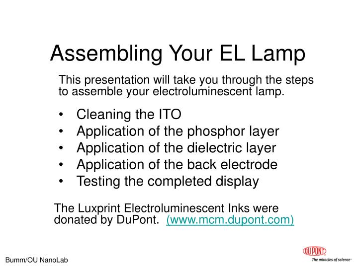
Assembling Your EL Lamp. This presentation will take you through the steps to assemble your electroluminescent lamp. Cleaning the ITO Application of the phosphor layer Application of the dielectric layer Application of the back electrode Testing the completed display.

E N D
Assembling Your EL Lamp This presentation will take you through the steps to assemble your electroluminescent lamp. Cleaning the ITO Application of the phosphor layer Application of the dielectric layer Application of the back electrode Testing the completed display The Luxprint Electroluminescent Inks were donated by DuPont. (www.mcm.dupont.com)
Overview of the EL Lamp 1 ITO (green) 4 conductive rear electrode (gray) etched electrode isolation bar. Conductive rear electrode layer connects to electrode bar (left)does not extend to image border (right) does not extend to edges of slide (top & bottom) phosphor (cyan) 2 phosphor layer extends to edgeof the isolation bar (left)to image border (right) to edges of slide (top & bottom) 5 Copper tape electrodes (brown) copper tape connects to the left (rear) electrode bar andto the right (front) electrode bar. dielectric (magenta) 3 dielectric layer nearly covers the isolation bar (left)extends to image border (right) to edges of slide (top & bottom) The layer thicknesses are greatly exaggerated!
Cleaning the ITO First set up the basic mask pattern Add the bar to separate the front and back electrodes. Using the rectangle tool make a rectangle taller than 1” and one grid unit wide. use the paint bucket tool to set the fill to white. • Set up PowerPoint for drawing • from the draw menu select ‘Grid & Guides’ • check ‘snap objects to grid’ • select grid spacing of 0.063” (1/16”) • check ‘Display grid on screen’ 3 Define the area Use the rectangle tool to draw a 1” square. 1 We actually want the bar thinner. Select the bar and then right click. From the pop-up menu select ‘format auto shape’ select the ‘size’ tab and adjust the width to 0.03” (You will need to type this.) 4 Make the fill black Select the square and use the ‘paint bucket’ 2
Designing Your Etch Mask(steps 5-8) Completing the basic pattern Select the left bar set the line color (outline) to ‘no line’ Select the right bar, set its fill color to black Group all three objectsselect all three objects, right click, from the pop-up menu, select grouping, select group. Position the bar select the bar and move it 2 grid spaces from the left. The right edge of the bar should be 2 grid spaces from the left. The leading edge of the object snaps to the grid, so the result depends on the direction you are moving. 5 7 2 grid spaces (1/8”) The area for your pattern. Now you have the basic pattern created. You can now add patterns between the left and right bars. For aesthetic reasons you will want to leave a margin of at least one grid unit around your pattern. 8 We also need to reserve space for the front electrode. Our design must fit in between. Duplicate the bar and position the duplicate 2 grid spaces form the right. 6 Area for your pattern If the two bars do not appear to have the same width, This could be an artifact of the display. Zoom the display, at higher magnification they should appear equal. 2 grid spaces (1/8”)
Designing Your Etch Mask(steps 9-12) Create a temporary guide It is useful to make a rectangle to define the pattern area. Add a rectangle to define your pattern area, shown in blue. Your will delete this later. 9 Fixing isolated areas. The pattern we want, enclose regions of ITO which are not connected to the front electrode contact. We can easily fix this by drawing black lines between the outside and the inside. Use several lines to insure connection. Some may fail. Use lines at least 1-1/2 pts wide. 11 What I have done is easier to see here 10 Draw your pattern inside the rectangle. Make sure it is black & white. No gray. Remember the mask will define where acid will remove ITO Finalizing your pattern When you are satisfied with your pattern erase the guide rectangle from step 9. Group all of the objects. This helps prevent parts of your mask from accidentally shifting. 12
Designing Your Etch Mask(steps 13-16) Final check Make sure the bar separating the front and the back electrode is clear. No part of your pattern should cross it. Are any parts of your pattern isolated? If so go to step 11. Because your pattern is only 1” square, you can put many on one sheet. It is a good idea to copy our mask pattern several times so that you have extra. 13 Test print you mask on paper You will use a laser printer to generate your mask by printing onto transparency film. Because transparency film does not grow on trees we will first make a test print on paper. It is best to perform the test print on the SAME printer you will use for the transparency. 14 PowerPoint wants to print white lines as black.To print what you see, go to ‘print’ from the ‘file’ menu, at the lower left under ‘print what’ select ‘color’ 15 Print your mask on transparency film. 16 Inspect you Finished Mask If you find defects in the black image use a Sharpie marker to cover the unwanted clear areas. When you are sissified with your mask your are ready for the photolithography.