Download
1 / 47
470 likes | 612 Views
A systematic study of cross-talk limitations in RPC timing. D. Gonzalez-Diaz, A. Berezutsky and M. Ciobanu for the CBM-TOF working group 15-10-2008. Index. 1. Cross-talk and timing. General remarks. 2. Measurements and comparison with FEM ( F inite E lement M ethod) description.

E N D
A systematic study of cross-talk limitations in RPC timing D. Gonzalez-Diaz, A. Berezutsky and M. Ciobanu for the CBM-TOF working group 15-10-2008
Index • 1. Cross-talk and timing. General remarks. • 2. Measurements and comparison with FEM (Finite Element Method) description. • 3. Design studies for operation in differential mode. • 4. Conclusions.
Basics (RPC rise-time) avalanche growth until onset of Space-Charge if Space-Charge present already at the level of the comparator, S would be even higher ! D.Gonzalez-Diaz, PhD(2006) P. Fonte et al., IEEE, Trans. Nucl. Sci. 49,3(2002)881 also measured with UV source and double-threshold technique
Basics (RPC rise-time) E=100kV/cm FT(V) time domain frequency domain
Basics (Q distribution and usual threshold) not including streamers D.Gonzalez-Diaz, PhD(2006) measured directly in the scope HADES 2003 prototype
Basics (fluctuations in time response) independent sources! We believe we can make σsing;e event~80 ps for large systems (CBM-Techincal Status Report 2005) ?
Cross-talk influence in timing (simple derivation) space-charge log(Vsignal) Vth exponential regime t variations in base-line due to cross-talk variations in time at threshold due to cross-talk
Cross-talk influence in timing (simple derivation) • Assumptions: • Within the same primary collision cross-talk extends up-to infinite time. • It does not depend on position. • Fluctuations in time of cross-talk signal are smaller than fluctuations coming from the avalanche charge distribution. • Pick-up strips are separated by a typical distance bigger than the area of influence of the avalanche. Charge sharing during induction can be neglected!. • Cross-talk influences only the first neighbour, coupling to it with a fraction of its amplitude F. • Cross-talk is small.
Cross-talk influence in timing (simple derivation) cross-talk: F=10% rough cross-talk (above threshold) subtle cross-talk (below threshold) events above threshold in neighbour: 20%
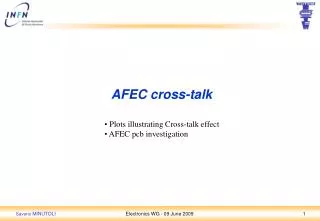
Different ways of shielding shielding vias shielding strips
Comparison with simulation signal injected from a fast scintillator trise~1ns
Cross-talk from cell with shielding vias(neighbour not terminated on the other side!)
Cross-talk from cell with shielding vias(to 1st and 2nd neighbour!)
simulation of the S coefficient scattering matrix coefficient to neighbouring anode (equivalently: fraction of signal transmitted)
Comparison with data from spectrum analyzer preliminary!
simulation of a realistic structure RPC structure: signal width = 22 cm, gap to next strip = 0.3 cm 16 gaps, 0.16 mm gap 0.3 mm glass 0.86 mm PCB propagation ofexponential signal with 200 ps rise-time in anode and cathode simultaneously (differential mode)
Transmission properties vias no vias
Transmission properties vias no vias
Transmission properties vias no vias
Transmission properties vias no vias
Transmission properties vias no vias
Transmission properties vias no vias
Transmission properties vias no vias
Transmission properties vias no vias
Conclusions (I) • Cross-talk levels at the level of 10% are capable of destroying timing RPC multi-hit performances. • Cross-talk influence depends critically on the ratio Vth/<Vsignal> and the signal rise-time. For timing RPCs it corresponds to a 'corner frequency' of 1.75 GHz at least (-3dB drop). • Aplac is a good tool for understanding fast signal propagation. • For the measured signals the quality of our groundings is well described by 'ideal grounding' in APLAC. • Detector box affects critically to signal properties. Without a proper description the simulation fails by factors.
Outlook • Elaborate the results a bit further to establish sound requirements. • Use this information to build a prototype. • Measure cross-talk in a realistic prototype. • Measure experimentally the charge-sharing during induction.
Conclusions (II) • Impedance matching does not help at all from the point of view of cross-talk, however it may allow for desired double-hit capabilities. • Detector matching is extremely complicated and does not fit at all to the required granularities. If impedance matching is requested, the granularity at the outer regions would require strips of 4 mm wide and 6 meters long. • How to get a matched detector?? (first of all, the resulting multi-strip configuration is only truly matched after ALL the corresponding cross-impedances are matched): • Build the detector with the impedance of the FEE. • Build the FEE and cables with the impedance of the detector. • Build the detector and the FEE and match the impedance with some driver. • Do not care about double-hit capabilities in the same strip (HADES).
Conclusions (III) suggestion: place the FEE inside the detector, reduce its input impedance and eliminate the problem of signal transmission in cables!