Download
1 / 61
610 likes | 760 Views
200 1 Simulation Seminar. Geometry Abstraction & Section Meshing. 2001. Geometric Abstraction and Meshing. Design Geometry Realities. Geometry Effects. Quickly pass through the model construction phase Engineering begins after the results are available.

E N D
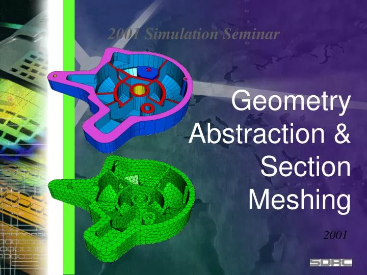
2001Simulation Seminar Geometry Abstraction & Section Meshing 2001
Geometric Abstraction and Meshing • Design Geometry Realities
Geometry Effects • Quickly pass through the model construction phase • Engineering begins after the results are available Geometry provides the most promise to CAE impacting design activities Geometry is the biggest inhibitor to meshing efficiency “Design Engineer needs complete, high quality mesh of any automotive component in less than ½ day”. Hiroyuki Umetani manager, Development Dept. Information Systems Toyota Motor Corporation
Post Processing Percentage of Time 9% Solve 4% Geometry Boundary Creation Conditions 42% 9% Mesh Generation 17% Prepare Geometry Repair Imported for Export Geometry 6% 13% SDRC, 1997 A Break-Down of the CAE Process • What is the most time consuming process?
Before Time Today 1 Iteration Direction of SDRC’s CAE • Much Focus on Pre-Processing • Automatic & Robust Tool for building FE Model
Improvements during MS5 - MS7 • Some examples of the reduction time to build FE Model 1/10 1/50
Powerful Geometry Abstraction • Part contains 300 surfaces. Abstracted to 24 meshing regions
Customer Endorsements • ZF Automotive supplier to many major OEM’s of Driveline and chassis technology • Complex parts/assemblies (I.e. transmission cases) • “Almost 30% development time saved by using I-DEAS Section Meshing Technology” Dr. Kelkel ZF, Germany
Typical Design Geometry • Topology Issues • small edges • compound edges • sliver surfaces • high aspect ratio • missing surfaces • topology too detailed • reconstruction
Small Edges • Force small element edges • Causes high distortions for elements larger than edge • Dictates element size
Sliver Surfaces • Narrow surface which causes distortions and stretched elements
Disconnected Surfaces • Surfaces which are not “stitched” together do not share the same edges • Causes discontinuous mesh that do not allow forces to transfer across the discontinuity
Poorly Parameterized Surfaces • Surfaces which do not have evenly spaced iso lines do not have evenly spaced parameter space in 3D • Results in skewed and stretched elements • Especially in imported geometry
Meshing algorithms • Bounded by surface shape and boundaries • can distort elements beyond usefulness • dictates element size
Section Meshing • Expands the boundaries of surfaces • relaxes mesh area therefore improving quality of elements • removes boundary and shape constraints that negatively effects meshing
Section Meshing • Permits edge connectors to be removed • Removes requirement of having at least one element/edge • Relaxes elements and therefore improves mesh quality
Too Much Detail • Small holes usually have adverse effect on mesh • increases number of nodes/elements in unimportant area of model • can distort elements because of local curvature • but are internal boundaries which meshing algorithms must address
Too Much Detail • Often only one single node is needed to represent hole for boundary condition definition • model more efficient
Too Much Detail • Topology Suppression • History Supported • requires integrated modeler • Automatic / Manual Modes • Loop Collapsed to Point • Curve Collapsed to Point • Ignores Small Edges
Solid Meshes • Section meshing applies to solids also • Sections can be used to map mesh volumes for brick elements generation
Section Meshing • Capture Analysis Intent • User Control • Puts the model size (degrees of freedom) within the control of the user • Does not change the geometry (surfaces, edges, . ) of the part • Overhead minimal because no additional geometry is created • all nodes are on original surfaces and elements can span surface boundaries • Integrity of part is intact In Short Section Meshing has become the preferred meshing approach to all types of parts
Where do I start? • I know I can abstract my model but with complex models • How do I find the problem areas? • What element size should I use? • How much time should I spend abstracting?
Where Do I Start? • Real Parts • Automatically combine surfaces until user criteria is met
Surface and Section Quality Checks • The meshing job is a balance of FEM size (element size) and how much interaction the user wants to go through to get the element size he wants • In the past modeling time was unpredictable because it was impossible to anticipate how many of these problem situations would arise Try element size Mesher Fail
Quality Check • Find small edges • Find sliver surfaces • Find small holes • Show me expendable connectors
Quality Checks • Highlight problem geometry
Quality Checks • How many bad surfaces do I have? • Indicates • how much work I have to do to make useable mesh based on criteria • if not many I know what element size this geometry will take • if checks are made on sections, then same indications are available and user knows how much work is left • Continue until all sections disappear
Section Mesh Layout • Remove Curve • Remove Connector • Remove Loop • Add Curve • Add Connector • Add Loop • Auto Create • Auto Remove Loop / Connector • Replace Curve • Replace Connector • Manual Create • Single Section Create • Delete Section • Section Check • Show Orphan Surface • Section Graphics Toggle • Surface Patch Generator • New Meshability Check • Display Adjacent • Display Opposite • Section Graphics Toggle
Results Isthmus Surface from IGES Collapsed region Resulting Single Section multi-looped section Mesh on the Section
Results Isthmus Section now combined with adjacent sections using new functionality Resulting Mesh
Results Isthmus Surface Resulting Section Resulting Mesh
MS8 Replace Curve Original Surface Replace A portion of one curve with the other
Replace Curve Eliminated the pinched area with Replace Curve Resulting Mesh
Replace Curve Replace Curve Maintains connection with other sections
Mid-Surface Challenges for Section Mesh A straight Automatic Pairing produces this Surface extend fail Surfaces aren’t trimmed back and stitched Surfaces aren’t extended to wall
Section Add Curve Midsurfaces not fully extended and walls not scarred Need to use Section Meshing to repair
Project surface boundary and replace User 1) Adds Curve projecting original edge of surface 2) Replace original curve with projected
Quality Checks • All geometric problems anticipated • Meshing reduced to one iteration in most cases
Meshing Issues - Tet Hex • Tet Hex meshing allow mixing of Parabolic Tets with Bricks • Multipoint Constraint elements (MPCs) tie up loose mid nodes
Element Project /Element, Orient Off Geometry, Project Element Collapse /Check Mesh, Element Collapse Meshing Issues - Manual Control
Element Extrude Normal Meshing Issues - Manual Control
Meshing Issues • Element Collapse (under the Quality Checks icon stack) • Collapse narrow (stretched) linear or parabolic triangular shells
Mesh Generations • Brick Elements from shell projection
Mesh Generation • Project Elements to Surface
Augmentation of Geometry • Geometric information; physical representation • Additional structure. • Calculation surface to measure energy propagation. • Contact regions, FEM or geometry based. • Weld attachments, reference series of locations • Non-geometric information; non-physical representation • interpolated surfaces. • lumped masses, springs, or beams. • gaps, coupled dofs, or constraint equations.
Adaptation of the FEM • Associative to design definition • geometry change • abstraction change • boundary conditions • loading conditions • surface mapping • Surface mapping/compare parts • domestic/imported
Mesh Generation • Many new options and features for mesh construction, including: • Automatic tetrahedral to hexahedral interface • Create Thickness Results • Element Extrude Normal • Element Project • Element Collapse
Improve Elements’ Quality • Nodes Drag • Viewing quality values • Improve surface mesh quality • Auto Settings during meshing • Automatic Mesh Checking & Improvement • Tetra Fix • Move Mid Nodes + Straighten Edge • Plump • Fix Flat tet elements
Replace Orphaned Surfaces Integrated CAE with 3D/CAD • Surfaces Mapping • Imported Geometry from other CAD Update Mesh on orphaned surfaces