Download
1 / 34
360 likes | 611 Views
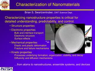
Electronic Structure and Transport Properties of Iron Compounds: Spin-Crossover Effects. Viktor Struzhkin. Collaborations. M. Eremets, I. Eremets Max-Planck Institute, Mainz, Germany A. Gavriliuk, I. Lyubutin Institute of Crystallography, RAS, Moscow, RUSSIA Optics and Theory

E N D
Electronic Structure and Transport Properties of Iron Compounds: Spin-Crossover Effects. Viktor Struzhkin
Collaborations • M. Eremets, I. Eremets • Max-Planck Institute, Mainz, Germany A. Gavriliuk, I. Lyubutin Institute of Crystallography, RAS, Moscow, RUSSIA Optics and Theory A. Goncharov, GL S. Ovchinnikov Institute of Physics, Siberian Branch of RAS, Krasnoyarsk, RUSSIA NFS, XES • W. Sturhahn, J. Zhao, S. Kharlamova, • P. Chow, M. Y. Hu • APS, ANL, Argonne, USA • J. F. Lin • LLNL
Spins and Magnetism P > Pc P < Pc Scope: electronic structure of Fe2+ and Fe3+ in octahedral sites
Theoretical approach • In the Mott-Hubbard theory charge fluctuationsdin djn din-1 djn+1are completely suppressed due to strong exchange and Coulombd - d interactionU • J.Zaanen, G.Sawadzky, J.Allen[PRLett 1985] showed that an another type of charge transfer () can be considered din din+1L, whereL – is a hole inp–valence band of anion • Depending on the ratio of parameters,which are related to hybridizationТ, the system can be (from the point of view the nature of the gapЕgap) : 1) Mott-Hubbard insulatord-d typeU<(Еgap U), 2) insulator (or semiconductor)with charge transfer U>(Еgap ), 3) d – metal <U andU<W/2 4) p – metalU<and<W
Bandwidth- versus filling-controlledmetal-insulator transition(Fujimori)
Mott-Hubbard transition under high pressure: bandwidth control
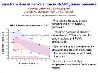
eg d t2g 10Dq Tanabe-Sugano diagramfor Fe+3ion andSpin crossover Fe3+- LS (S = 1/2) Fe3+- HS (S = 5/2) Usp
Magnetic collapse in transition metal oxides Cohen, Mazin, Isaak, Science 1997 High-spin to low-spin transition I. Jackson and A. E. Ringwood (1981) ΔG = ΔE – PΔV + TΔS ΔE = Nn{π - Δ(r)}, Δ~ Δ0(r0/r)5 For cubic (B1) FeO: Ptr=50 GPa R. E. Cohen et al., MRS Symp proc. 1998
X-ray emission spectroscopy as a local magnetic probe Axial Radial Radial
High-spin to low-spin transition in FeS J.-P. Rueff , C.-C. Kao,V. V. Struzhkin, J. Badro, J. Shu, R. J. Hemley, and H. K. Mao , Phys. Rev. Lett. (1999) Radial
Spin-crossover transition in ferropericlase J. Badro et. al., Science (2003) Mg0.83Fe0.170
Nuclear inelastic scattering set-up (W. Sturhahn, E. Alp, M. Hu)
Reduced radiative conductivity of low-spin (Mg,Fe)O in the lower mantle A. Goncharov, V. Struzhkin, and S. Jacobsen The observed changes in absorption are in contrast to prediction and are attributed to d-d orbital charge transfer in the Fe2+ ion. The results indicate low-spin (Mg,Fe)O will exhibit lower radiative thermal conductivity than high-spin (Mg,Fe)O, which needs to be considered in future geodynamic models of convection and plume stabilization in the lower mantle.
Comparison of Mössbauer and X-ray emission results for FeO M. P. Pasternak et al . Phys. Rev. Lett.(1997) J. Badro et al. Phys. Rev. Lett. (1999) Radial
Insulator-metal transition in FeO 41 GPa 113 GPa
Singe crystals enriched with the Fe-57 isotope Fe3+ Samples: • Fe B O3 • R Fe3(BO3)4(R = Gd) • Y3 Fe5 O12
Y3Fe5O12 Electronic transition Changes in the crystal color under pressure increase and decrease 41 GPa 19 GPa 50 GPa 0 GPa 13 GPa 32 GPa
Structural, magnetic, electronic and spin transitions at high pressures FeBO3 at 53 GPa collapse of the unit-cell volume by ~ 9 % atP = 46 GPathe insulator- semiconductor transition atP = 46 GPa magnetic collapse with the HS LS transition
Structural, electronic and spin transitions at high pressures GdFe3(BO3)4 at 26 GPa collapse of the unit-cell volume by ~ 8 % atP = 43 GPathe insulator- semiconductor transition atP = 43 GPa the HS LS transition
Structural, magnetic, electronic and spin transitions at high pressures Y3Fe5O12 at 48 GPa srtuctural amorphyzation atP = 50-55 GPathe insulator- metal transition atP = 48 GPa magnetic collapse with the HS LS transition
Bi Fe O3 :Multiferroic BiFeO3 - belongs to ferro-magneto-electric materials (multiferroics) which have both a spontaneous electrical polarization and a spontaneous magnetization. Between known multiferroics, it has a record high the antiferromagnetic Neel temperature (TN = 643 K) and the ferroelectric Curie temperature (TC= 1083 K)
BiFeO3 Electronic transition from the insulating to highly conducting state. Mott ? 54.5 GPa 7.2 GPa
BiFeO3 Pressure – temperature dependence of resistivity At 40 – 55 GPa the resistance drops by 107 (metallization)
Structural, magnetic, electronic and spin transitions at high pressures Bi Fe O3 near 45 GPa srtuctural transition atP = 45-55 GPathe insulator- metal transition atP = 47 GPa magnetic collapse with the HS LS transition
Theoretical approach • S. G. Ovchinnikov [JETP Letters, 2003] Main parameter is the effectiveHubbard energyUeff Ueff = E0(d 4) + E0(d 6) - 2 E0(d 5) LPPP < Pc S = 2 S = 2 S = 5/2 HPPP > Pc S = 1 S = 0 S = 1/2
ELECTORON STRUCTURE of FeBO3 and GdFe3(BO3)4 [S.G. Ovchinnikov and S.A. Kharlamova, JETP Letters, 2003; 2004] SECfor Fe: а)d-d- transitions b)charge transfer transitions p6d5 p5d6 electron creation Fe3+ Fe2+: с= E (5Т2, d6) – E (6A1, d5) hole creation Fe3+ Fe4+:=E0(6A1,d5) – E0(6A1,d4) By Raccah parameters : с=d +5 A +14 B – 0.4 =d +4 A – 14 B +0.6 Then the Hubbard effective parameter is: Ueff =c– = А+28В–=4.2 eV
7 Ueff 4.2 1.45 Density of electronic states of GdFe3(BO3)4 in within multi-electronicp - d model at ambient and high pressure Р Рс ELECTRON STRUCTUREof FeBO3 and GdFe3(BO3)4in MULTIELECTRON MODEL at AMBIENT and HIGH PRESSURE S.G.Ovchinnikov. JETP Lett. (2003) The effective Hubbard parameter: Ueff=c - = E0(d4)+E0(d6)-2E0(d5) PPc S=2 S=2 S=5/2 PPcS=1 S=0 S=1/2 Ueff =c - = А+9В-7С 1.45 eV
Theoretical approaches Fe3+ Fe2+ • S. G. Ovchinnikov [JETP Letters, 2003] FeO?
Bandwidth- versus filling-controlledmetal-insulator transition(Fujimori) HS-LS U-control