Download
1 / 14
150 likes | 289 Views
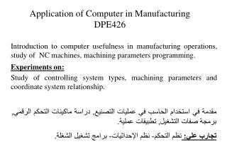
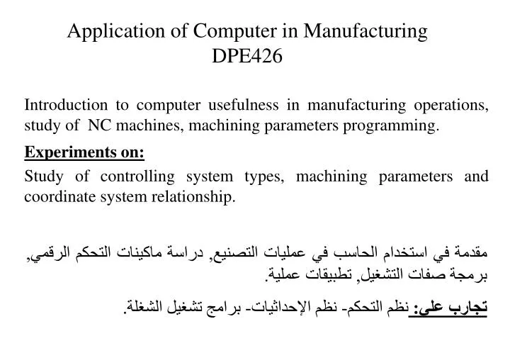
Application of Computer in Manufacturing DPE426. Introduction to computer usefulness in manufacturing operations, study of NC machines, machining parameters programming. Experiments on: Study of controlling system types, machining parameters and coordinate system relationship.

E N D
Application of Computer in Manufacturing DPE426 Introduction to computer usefulness in manufacturing operations, study of NC machines, machining parameters programming. Experiments on: Study of controlling system types, machining parameters and coordinate system relationship. مقدمة في استخدام الحاسب في عمليات التصنيع, دراسة ماكينات التحكم الرقمي, برمجة صفات التشغيل, تطبيقات عملية. تجارب علي: نظم التحكم- نظم الإحداثيات- برامج تشغيل الشغلة.
Grading: Final-term Examination 90 degrees Attendance and participation 10 degrees Mid-Term Examination 20 degrees Oral Examination. 30 degrees Table of contents : Chapter 1:Introduction to CAM Chapter 2: Automation in production systems Chapter 3:Sensors, Actuators & other control system components Chapter 4:Numerical control systems (NC) Chapter 5:Industrial Robotics Chapter 6:Introduction to material handling Chapter 7:Group technology Chapter 8:Computer aided process planning.
Ref. Materials • Automation, Production systems, and Computer-Integrated Manufacturing (2nd edition), M.PGroover, Prentice Hall, 2001. • CAD/CAM/CIM (3rd edition), P. Radhakrishnan, S. Subramanian, V. Raju, New Age International (P) Ltd., Publishers, 2008. • Principles of CAD/CAM/CAE systems, Kunwoo Lee, Addison Wesley Longman, Inc., 1999. • CAD/CAM: Computer-aided design and manufacturing, Groover, M.P., Zimmers, E.W. • CAD/CAM principles, practice and manufacturing management, 2nd Edition, McMahon, C., Browne, J. Web page; www.staff.zu.edu.eg/awafa Email; awafa971@gmail.com , awafa@zu.edu.eg
Process planning Design engineering Product concept Drafting Production scheduling Production Quality control CHPTER 1 INTRODUCTION TO CAM Before discussing the different usage of computer in manufacture system the product cycle and the impact of computer in this cycle will be shown. 1.1 The Product Cycle Customers and markets Order new equipment and tools Fig. 1.1 The product cycle
CAD Computer aided drafting and documentation Computer aided process planning Process planning Design engineering Product concept Drafting Computerized scheduling, material requirements planning and shop floor control Production scheduling Production Quality control Computer aided quality control. Computer controlled robots, machine, etc. The use of computer in the product cycle. Customers and markets Order new equipment and tools Fig. 1.2 The impact of computer in product cycle
1.2 Computer Aided Design (CAD) • Computer-aided design (CAD) can be defined as the use of computer system to assist in the creation, modification, analysis, or optimization of a design. • Reasons for implementing a computer aided design systems: • Increase the productivity of the designer. • Improve the quality of the design. • Improve communications; It provides better engineering drawings, fewer drawing errors, better documentation of the design and greater legibility. • Create a database for manufacturing; In the process of creating documentation for the product design most of the required data base to manufacture product is created. Such as, geometries and dimensions of the product and its components, materials specifications for components, bill of materials etc.
Design process: • Recognition of needs; Involves problems exists for correction and perception of a new product. • Definition of the problem; involves the specification (physical and functional characteristics, cost, quality, and operation performance. • Synthesis and analysis; are closely related and highly iterative in the design process. A certain component or subsystem is taken by the designer, subjected to analysis, improved through this analysis procedure. The process is repeated until the design has been optimized with the constraints imposed on the design. • Evaluation; is concerned with measuring the design against the specifications established in the problem definition phase. This requires the fabrication and test of a prototype model. • The presentation of the design; The documentations include drawings, material specification, assembly lists etc.
Geometrical modeling Engineering analysis Automated drafting The design process CAD Recognition of need Problem definition Synthesis Design review and evaluation Analysis and optimization Evaluation Applications of Computers for Design Presentation Fig. 1.3 Application of computer in design
1- Geometric modeling; is mathematical description of the geometry of an object. • This helps the designer to construct the graphical image of the object on the CRT screen of the ICG (interactive computer geometry) system by: • Commands for generation basic elements. • Commands for transformations. • Commands for joining the various elements into the desired objects. • The computer converts the commands into mathematical model, stores, and displays it as an image on CRT. This model can be called from the data files for review or analysis. • Methods for representing the object in geometric modeling: • Wire frame. • Surface representation • Solid modeling
2- Engineering analysis • Analysis of mass properties • Finite-element analysis • 3- Design review and evaluation • Check the accuracy of the design (dimensions errors, interference check, kinematics – motion evaluation) 4- Automated drafting Besides these four functions CAD systems can used for classified and coding the parts (collecting the similar parts into groups). • BENEFITS OF CAD • Productivity improvement in design • Shorter lead time • Design analysis • Fewer design error. • Great accuracy in design calculations • Standardization of design, drafting, and documentation • Drawings are more understandable • Improved procedures for engineering changes
1.3 Computer aided Manufacturing (CAM) Computer-aided manufacturing (CAM) can be defined as the use of computer systems to plan, manage, and control the operations of a manufacturing plant through either direct or indirect computer interface with the plant’s productions resources. The applications of computer manufacturing fall into two broad categories: • Computer monitoring and control (direct applications). • Computer monitors the manufacturing process involving a direct interface with it for the purpose of observing the process and associated equipment and collecting data from the process. The control of the process remains in the hand of human operators. • Computer process control controlling the manufacturing operations based on the observations collecting in the monitoring process. The computer issues signals directly to the manufacturing process based on the control algorithm contained in its software.
Manufacturing support applications (indirect applications); • The computer is used in support the production operations, but there is no direct interface between the computer and the manufacturing process. • Numerical control part programming by computers. • Computer automated process planning. • Production scheduling. • Material requirements planning. • Shop floor control. • CREATING THE MANUFACTURING DATA BASE • In the conventional manufacturing cycle, engineering drawing were prepared by the designer and then used by manufacturing engineers to develop the process plan. This is both time consuming and involved duplication of effort. • In an integrated CAD/CAM system, a direct link is established between product design and manufacturing. The goal of CAD/CAM is not the automation of certain phase of design or manufacturing but to automate the transition from design to manufacturing. The database includes all the data on the product, generated during the design process (geometry data, bill of materials and parts list, materials specifications, etc).
CAD Production Data base CAM Geometrical modeling Tool design Engineering analysis NC programming ICG Design review and evaluation CAPP Automated drafting Production planning. Fig. 1.4 The CAD/CAM relations
Benefits in manufacturing • The CAD/CAM data base which used in the following areas; • Tool and fixture design for manufacturing. • Numerical control part programming. • Computer aided process planning. • Assembly lists for production. • Computer aided inspection. • Robotics planning • Group technology. • Shorter manufacturing lead times through better scheduling.