CAD to G4/ROOT Geometry Transfer Tool
320 likes | 359 Views
Streamline creation of G4/ROOT-compatible geometry from CATIA V.5 CAD system for radiation simulation. Overcome differences in solid body representation between CAD and G4/ROOT. Improve efficiency and accuracy in simulations.

CAD to G4/ROOT Geometry Transfer Tool
E N D
Presentation Transcript
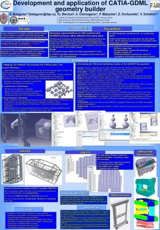
CATIA-G4/Root Geometry Builder. 1- Institute for Theoretical and Experimental Physics (ITEP), Moscow, Russia 2- Bauman Moscow State Technical University, (BMSTU) Moscow, Russia 3- GSI - Helmholtzzentrum für Schwerionenforschung GmbH, Darmstadt, Germany (Helmholtz Centerfor Heavy Ion Research) S. Belogurov1,2,*(belogurov@itep.ru), Yu. Berchun2, A. Chernogorov1,*, P. Malzacher3, E. Ovcharenko1,2,*, A. Semennikov1 * -FRRC fellows
Outline • Introduction • Motivation • The method • An example • Plans S. Belogurov et al. FRRC session, Dec. 12-th, 2010, Obninsk
Introduction Design optimization requires iterative exchange of geometry and material info CAD system simulation tools For mechanical, thermal, and some of electromagnetic software the transfer is automated. For radiation simulation packages that’s not a case. In some cases automated geometry transfer is possible, but result is not optimized for simulations, and computations are too slow for big assemblies and complex shapes. S. Belogurov et al. FRRC session, Dec. 12-th, 2010, Obninsk
Introduction The most popular software for simulation of particle interactions and propagation in matter and data analysis are GEATN4 and ROOT. Both Geant4 and ROOT use the same geometry representation which differs a lot form one in CAD systems. Geant4/ROOT geometry can be transferred via GDML files We are presenting a tool, which allows to facilitate creation of G4/ROOT-compatible geometry from the CAD system CATIA v.5 (used in CERN, GSI and other labs) The work was reported at SECESA2010 and CHEP2010 conferences S. Belogurov et al. FRRC session, Dec. 12-th, 2010, Obninsk
Motivation Geometry representation in CAD and G4/ROOT The difference is twofold: in the description of solid bodies and in the hierarchy of assemblies. In CAD systems solid bodies are built using a wide class of surfaces and curves in advanced boundary representation (BRep). S. Belogurov et al. FRRC session, Dec. 12-th, 2010, Obninsk
Motivation Geometry representation in CAD and G4/ROOT The difference is twofold: in the description of solid bodies and in the hierarchy of assemblies. In G4/ROOT the Constructive Solid Geometry (CSG) is used. Building blocks are primitives. Currently 21 primitives are implemented. Some of them are shown S. Belogurov et al. FRRC session, Dec. 12-th, 2010, Obninsk
Motivation Geometry representation in CAD and G4/ROOT The difference is twofold: in the description of solid bodies and in the hierarchy of assemblies. In G4/ROOT the Constructive Solid Geometry (CSG) is used. Simple solids can be combined using Boolean operations (union, subtraction, intersection) Result of Boolean operation is a solid. It can participate in further Boolean operations S. Belogurov et al. FRRC session, Dec. 12-th, 2010, Obninsk
Motivation Geometry representation in CAD and G4/ROOT The difference is twofold: in the description of solid bodies and in the hierarchy of assemblies. In CAD hierarchy a minimal unit is a solid body (part). Products (assemblies) and subproducts are only logical units – all the materials are assigned to solid bodies inside the part files or to parts S. Belogurov et al. FRRC session, Dec. 12-th, 2010, Obninsk
Motivation Geometry representation in CAD and G4/ROOT The difference is twofold: in the description of solid bodies and in the hierarchy of assemblies. L1(Box1,Vacuum ) In the G4/ROOT hierarchy there are three conceptual layers: • G4VSolid: shape, size • G4LogicalVolume: material, MF, sensitivity, daughter volumes, etc. • G4VPhysicalVolume: position and rotation of an instance of the logical volume inside its mother S. Belogurov et al. FRRC session, Dec. 12-th, 2010, Obninsk
Motivation Geometry representation in CAD and G4/ROOT The difference is twofold: in the description of solid bodies and in the hierarchy of assemblies. L1(Box1,Vacuum ) L2(Box2, Plastic ) In the G4/ROOT hierarchy there are three conceptual layers: • G4VSolid: shape, size • G4LogicalVolume: material, MF, sensitivity, daughter volumes, etc. • G4VPhysicalVolume: position and rotation of an instance of the logical volume inside its mother S. Belogurov et al. FRRC session, Dec. 12-th, 2010, Obninsk
Motivation Geometry representation in CAD and G4/ROOT The difference is twofold: in the description of solid bodies and in the hierarchy of assemblies. L1(Box1,Vacuum ,3L2) L2(Box2, Plastic ) In the G4/ROOT hierarchy there are three conceptual layers: • G4VSolid: shape, size • G4LogicalVolume: material, MF, sensitivity, daughter volumes, etc. • G4VPhysicalVolume: position and rotation of an instance of the logical volume inside its mother S. Belogurov et al. FRRC session, Dec. 12-th, 2010, Obninsk
Motivation Geometry representation in CAD and G4/ROOT The difference is twofold: in the description of solid bodies and in the hierarchy of assemblies. L1(Box1,Vacuum ,3L2) L2(Box2, Plastic ) In the G4/ROOT hierarchy there are three conceptual layers: • G4VSolid: shape, size • G4LogicalVolume: material, MF, sensitivity, daughter volumes, etc. • G4VPhysicalVolume: position and rotation of an instance of the logical volume inside its mother L3(Cyl1,Cu) L4(Box3,Fe) S. Belogurov et al. FRRC session, Dec. 12-th, 2010, Obninsk
Motivation Geometry representation in CAD and G4/ROOT The difference is twofold: in the description of solid bodies and in the hierarchy of assemblies. L1(Box1,Vacuum ,3L2) L2(Box2, Plastic , L3, 2L4) In the G4/ROOT hierarchy there are three conceptual layers: • G4VSolid: shape, size • G4LogicalVolume: material, MF, sensitivity, daughter volumes, etc. • G4VPhysicalVolume: position and rotation of an instance of the logical volume inside its mother L3(Cyl1,Cu) L4(Box3,Fe) S. Belogurov et al. FRRC session, Dec. 12-th, 2010, Obninsk
Motivation Geometry representation in CAD and G4/ROOT The difference is twofold: in the description of solid bodies and in the hierarchy of assemblies. L1(Box1,Vacuum ,3L2) L2(Box2, Plastic , L3, 2L4) In the G4/ROOT hierarchy there are three conceptual layers: • G4VSolid: shape, size • G4LogicalVolume: material, MF, sensitivity, daughter volumes, etc. • G4VPhysicalVolume: position and rotation of an instance of the logical volume inside its mother L3(Cyl1,Cu) L4(Box3,Fe) • - Any logical volume is made of a material • - Unlike a part in CAD systems, any logical volume may be a mother for placing smaller volumes inside. • Any intersections of volumes’ boundaries are forbidden. • TheWorld is the biggest logical volume, it can not be positioned. S. Belogurov et al. FRRC session, Dec. 12-th, 2010, Obninsk
Motivation Preparing any geometry for MC simulations one has to keep in mind two issues: 1. Required Detalization For a detector with poor position resolution, description should be less accurate than for more precise device. Choosing appropriate level of detalization, one can reduce significantly required computational time and memory. Examples: a threaded hole in a flange with a screw inside is equivalent for MC to a bulk piece of metal; for peripheral equipment, sometimes, just a simple solid filled with a correct mixture of materials is sufficient. S. Belogurov et al. FRRC session, Dec. 12-th, 2010, Obninsk
Motivation Preparing any geometry for MC simulations one has to keep in mind two issues: 2. Optimization for simulations A couple of tricks. - Minimization of the number of volumes. E.g. a module of the sampling calorimeter: In CADmodel – lead and scintillator plates. For G4 simulations scintillator plates are inserted into the bulk Pb mother volume. S. Belogurov et al. FRRC session, Dec. 12-th, 2010, Obninsk
Motivation Preparing any geometry for MC simulations one has to keep in mind two issues: 2. Optimization for simulations A couple of tricks. - Avoiding unions helps to accelerate simulations. E.g. CAD and G4/ROOT representations of a section of the beampipe for CBM experiment at FAIR (Cylinder, Sphere, Cone. No overlaps, no unions) S. Belogurov et al. FRRC session, Dec. 12-th, 2010, Obninsk
Motivation Thus, our tool allows to facilitate creation of G4/ROOT-compatible geometry from the CAD system CATIA v.5. Itis targeted on scientists who understand what geometry representation and level of detalization are optimal for given simulation task. Sacrificing automation of the geometry transfer we gain optimization For usage of the tool one should get familiar with limited (but powerful) measurement, construction, and visualization functionality of CATIA and our plugins. S. Belogurov et al. FRRC session, Dec. 12-th, 2010, Obninsk
The method Implementation of primitives as parameterized User Defined Features (UDF) in CATIA. The UDFs are placed into G4Catalog. For realization of Boolean combinations CATIA operations Add, Remove and Intersect are used. S. Belogurov et al. FRRC session, Dec. 12-th, 2010, Obninsk
The method File structure for representation of a LogicalVolume. PartBody contains a parameterized solid and material. Unparameterized solid copy of the PartBody is published Solids, published in files corresponding to smaller LogicalVolumes can be inserted into the tree with positioning. They represent daughter volumes M d d d S. Belogurov et al. FRRC session, Dec. 12-th, 2010, Obninsk
The method Initially, files containing only PartBodies with material and publication should be prepared. Then specially designed VBA macro helps to insert with positioning a copy of a LogicalVolume as a daughter PhysicalVolume into a destination part. S. Belogurov et al. FRRC session, Dec. 12-th, 2010, Obninsk
The method 3 methods of multiple instantiation are implemented Replica - matches with G4ReplicaVol Array - copied objects can be inserted into an intermediate logical volume SimplePlacement Array - intermediate volume is only a convenient reference frame S. Belogurov et al. FRRC session, Dec. 12-th, 2010, Obninsk
The method At the end the tree is analyzed and GDML file is exported. Import of GDML files into CATIA is implemented as well S. Belogurov et al. FRRC session, Dec. 12-th, 2010, Obninsk
The method • Illustration of the procedure. • Three Part files are loaded. • Slice is twice inserted and positioned inside the Cylinder • Cylinder is positioned inside the World (Box) • Geometry exported to GDML and read by ROOT S. Belogurov et al. FRRC session, Dec. 12-th, 2010, Obninsk
The method For transferring geometry, one has to load an existing CAD model first. Then, using powerful measurement, construction, and visualization functionality of CATIA and our tool, a G4/ROOT compatible geometry can be built. Examples of measurements in CATIA S. Belogurov et al. FRRC session, Dec. 12-th, 2010, Obninsk
Examples GLAD – Large Aperture SC Diplole Magnet for R3B experiment at FAIR. Consists of 4 SS and Cu layers of complicated shapes with ribs. All transferred to G4/ROOT. One of the shells is discussed here S. Belogurov et al. FRRC session, Dec. 12-th, 2010, Obninsk
Examples Cylinders, Tori, and Spheres, but length and radii of cylinders are modified : General shape is violated, but no slits –good for simulations Cylinders, Tori, and Ellipsoids: General shape is reproduced, but the shell has slits – bad for simulations S. Belogurov et al. FRRC session, Dec. 12-th, 2010, Obninsk
Examples LHCb VELO CAD model LHCb VELO read from GDML S. Belogurov et al. FRRC session, Dec. 12-th, 2010, Obninsk
Examples Crystal calorimeter for R3B. General and partial views S. Belogurov et al. FRRC session, Dec. 12-th, 2010, Obninsk
Examples Crystal calorimeter for R3B.G4/ROOT-like representation of a slice of CFC boxes and entire crystal array S. Belogurov et al. FRRC session, Dec. 12-th, 2010, Obninsk
Plans for further development - Enhancement of the set of implemented primitives - Improvement of the G4Materials catalog in CATIA - Implementation of checkers for CSG tree structure and volume overlaps - Adaptation of the CATIA Digital Mockup (DMU) optimizer for automatic fit of parameterized CSG models to existing parts - Case study and best practice elaboration S. Belogurov et al. FRRC session, Dec. 12-th, 2010, Obninsk
Plans for further development - Enhancement of the set of implemented primitives - Improvement of the G4Materials catalog in CATIA - Implementation of checkers for CSG tree structure and volume overlaps - Adaptation of the CATIA Digital Mockup (DMU) optimizer for automatic fit of parameterized CSG models to existing parts - Case study and best practice elaboration Thankyou for yourattention! S. Belogurov et al. FRRC session, Dec. 12-th, 2010, Obninsk