Download
1 / 15
160 likes | 367 Views
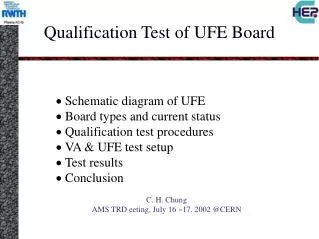
Qualification Test of UFE Board. · Schematic diagram of UFE · Board types and current status · Qualification test procedures · VA & UFE test setup · Test results · Conclusion C. H. Chung AMS TRD eeting, July 16 ~17. 2002 @CERN. Schematic Diagram of UFE. Applied Power.

E N D
Qualification Test of UFE Board · Schematic diagram of UFE · Board types and current status · Qualification test procedures · VA & UFE test setup · Test results · Conclusion C. H. Chung AMS TRD eeting, July 16 ~17. 2002 @CERN
Schematic Diagram of UFE Applied Power 12 bit ADC AD7476 HCC Chip VA32 HDR12 Preamp. Shaping Multiplexing Peak. T = 2.4ms Power:55mW
UFE Board Types UFE45M21 UFE45S17 ADC VA Op. Amp UFE90S96 UFE90M18 UFE development made up to the present
Test Procedures Measurements : Gain, Pedestals, Noise, Linearity, Connectivity More Qualification Tests · Mechanical Vibration ·Thermo Vacuum · EMI Production VA Hybrid · Peaking Time = 2.4 ms · Gain = 2.0 [ADC counts / fC] · Pedestals and Noise · All channels within ± 1% of the mean gain · All channels within 3% non-linearity · Connection test with external CAL UFE w.o VA
VA Hybrid Test Setup VA-DAQ setup * IDE Co. * Type of VA-chip: VA32HDR12 * Number of channels/chip: 32 * Number of chips/board: 1 * Value (pF) of calibration capacitor:10.00E+0 Labview w. ROOT VA DAQ PCB and Adapter board
VA Test Results(1) Signal waveform of channel Oscilloscope Gain fitting vs. input charge Peaking time & Linearity / channel
VA Test Results (3) Typically all channels within 1% of the mean gain Mean = 1.198 [mV/fC], Sigma = 0.00337 Click to add text
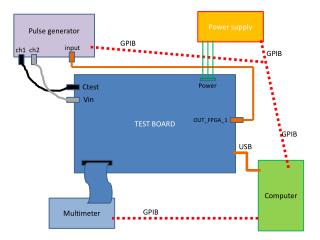
UFE Board Test Setup WIN NT CVI, ROOT Control signal Real mode : Pedestal and Noise CAL mode : Gain and Nonlinearity 4m Board Box Block diagram of DAQ system
UFE Test Results (1) Gain = 2.01 [ADC counts/fC] Noise = 1.705 ADC counts MIP signal in TRD = 55 [fC] @80% Xe + 20%CO2, gain = 3000(3.5´105 e-) S/N = 55/0.86 = 64 One Channel Pedestals and Gain linearity
UFE Test Results (2) Pedestals and Noise
UFE Test Results (3) Non-Linearity = [Fit-Measured]/Fit upto 1.5[pC] Linear range : 0~1.5pC within 2% nonlinearity
UFE Test Results (4) External Connection Test
Conclusion Qualification test setup for VA and UFE board is ready and working successfully. 40 VA Hybrid were tested and two chips were malfunctioning. 12 UFE boards were produced and tested. Pedestal, Noise, Gain, Linearity, Nonlinearity, Peaking Time, Connectivity /Channel/ VA chip/ UFE-Board Some problems are under investigation. Defect on VAs after soldering with UFE, connectivity improvement. Calibration const. DB : data sheet in ASCII format on the WWW. http://accms04.physik.rwth-aachen.de/~chchung/ams/trd/ufe/