Essential Tasks Before the Beam Arrival
130 likes | 253 Views
This to-do list outlines crucial tasks that need to be completed before the expected beam arrival in mid-June. Key tasks include generating a new trigger matrix for beam testing, installing an RF signal discriminator, checking output results in the Lv1 and Lv2 modules, testing connections between the v1495 and slow control, and verifying FPGA code functionality. Additionally, methods to manage slow control for firmware verification are addressed to prevent damage from radiation. Timelines for completing these tasks are highlighted to ensure readiness for the beam.

Essential Tasks Before the Beam Arrival
E N D
Presentation Transcript
To-do-list and schedule Shiuan-Hal,Shiu
Things need to do before beam comes • Generate new trigger matrix for test beam base on the final geometry.(1) • Install a discriminator for RF signal and arrange the cable.(2) • Check the output result in Lv1 and Lv2 module to make sure it fit our expect.(3) • Test the connection between v1495 and slow control.(4) • Test new FPGA code.(5) • Driver for data readout.(6) • Generate real beam FPGA code and test it.(7) • Connect the v1495 output to trigger supervisor.(8)
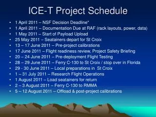
Time table • Assume the beam will come in middle June. (6)Driver for data readout Geometry and FPGA (7)Generate real beam FPGA code and test Today (1)Generate new trigger matrix Beam (2)RF and Cable arrangement (8)Connect the output to trigger supervisor (3)Check lv1 lv2 (4)Test connect with coda (5)Test new FPGA code
Wire connection and internal delayand geometry • Wire connection are all done, but I want make it looks more beautiful.(1~2 days) • Internal delay measurement: Ting suggests that we can replace the v1495 modules by some TDCs and trigger it by NIM logic, then we can get the relative delay values about all the channels.(after the beam comes) • Geometry and magnetic field strength: I have ask Paul about the geometry and magnetic strength this morning, and the answer is still not decided but he can give me the answer before this weekend. (3 days)
FPGA data collection and retiming part design RF connection? • This morning I have asked Dr. Wu about the FPGA data-lost problem, he will come here to check the problem before this weekend. After Dr. Wu has repaired this I’ll spend 3days to test it. • RF connection: Install a discriminator for RF signal in the experimental hall and test it.(1 day)
Trigger matrix logic and coding • Trigger matrix and look up table for test beam are all done. Now, the Lv1 track finder will send the Pt information (bend plane) and station 4 hit pattern (non-bend palne) to Lv2 track correlator. • I will spend 3 days to check all the Lv1 and Lv2 v1495 to make sure they work like we expect.
Connection with coda • The connection between v1495 and trigger supervisor still not done.(2 days) • Slow control: To prevent the FPGA and EPROM on v1495 damaged by radiation, we need to set up a method to make sure the firmware in all v1495 are correct all the time. We can connect the v1495 system with the slow control system, then use the slow control system to check the v1495 every minute. When the check process return some errors, then the system starts the recovery. The driver for slow control(upload firmware, reflash firmware, check firmware) are all done, but still not tested yet.(2 days)
Another things need to do • Dr. Wu suggests an auto delay calibration to calibrate the internal delay for each v1495 channels. This calibration will save all fired pattern in v1495 in each trigger to our data stream. This process needs transfer some data in v1495 to coda. The driver is almost done, but without any test. I will spend 1 day to finish the driver for data readout. And discuss with Kaz to test the total dead time for this process. After we make sure this function can work I’ll start add the automatic timing adjustment into the driver.
For real beam • The only different between real beam and test beam for v1495 is the trigger matrix. For test beam the trigger matrix only contains the information of St.2,3,4. For real beam the trigger matrix contains the information about St. 1,2,3,4 and three out of four design. I’ll spend a week to finish the code generator for real beam and test it.