Hydraulic Structures for Discharge Measurement
220 likes | 983 Views
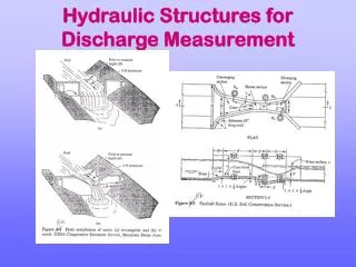
Hydraulic Structures for Discharge Measurement. Flow Measurement. Measurement Approaches. Direct methods (stream gaging) Current-meter method Floats Tracer-dilution technique Ultrasonic method Electromagnetic method. Measurement Approaches. Hydraulic Devices Weirs and notches Orifices

Hydraulic Structures for Discharge Measurement
E N D
Presentation Transcript
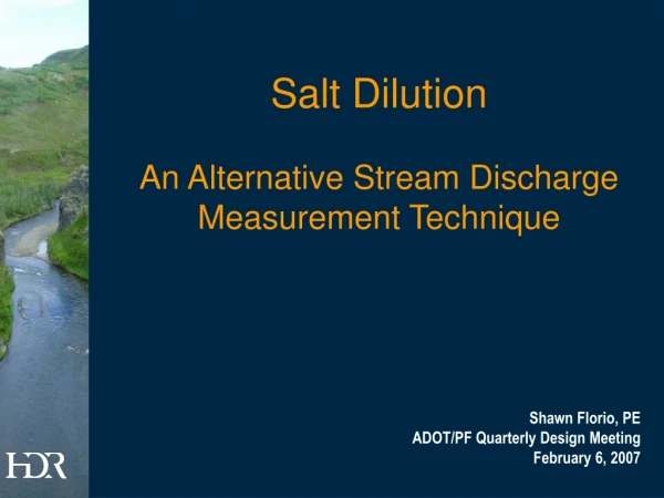
Measurement Approaches • Direct methods (stream gaging) • Current-meter method • Floats • Tracer-dilution technique • Ultrasonic method • Electromagnetic method
Measurement Approaches • Hydraulic Devices • Weirs and notches • Orifices • Flumes • Indirect Techniques • Slope-area method • Rating Curve
Definition of Terms • Stage: Height of water surface above a fixed datum • Rating: Relationship between stream stage and discharge • Control: Feature that results in a one-to-one relationship between stage and discharge
Measuring Velocity • Current meters • Cup-type (Price and pygmy) • Propeller type • Inductance V = a + bN where V = flow velocity; a = starting velocity to overcome mechanical friction; b = equipment calibration constant; N = revolutions/sec
Measuring Velocity • Pitot Tubes: Suitable only for clean water • Floats: Suitable for straight channel, V = L/T • .
Depth < 0.6m ; 0.6 water depth from the water surface = V V 0.6d + V V 0.2d 0.8d = £ £ V 0.6m Depth 2m 2 + + V 2V V 0.2d 0.6d 0.8d = ³ V Depth 2m 4 Mean Flow Velocity Estimation • Mean Velocity
Stage-Discharge Ratings • If it is not possible to install a weir or flume (large channel), need to develop a stage-discharge rating • 3 basic types • Simple stage-discharge • Control produces one-to-one rating • Slope-stage-discharge • Velocity-stage-discharge
Storage Hysterisis • In natural rivers, the H-Q relationship in general appears to be a loop, rather than single-valued.
Simple Rating • In general, ratings in natural channels follow a logarithmic shape (power function) • Rating has an offset at the “point of zero flow” • The point of zero flow can be determined graphically
Use of Manning Equation • Stage is also related to the outflow via a relationship such as Manning's equation
By Manning formula: 1 1 æ ö h 2 2 L = = Q K S K ç ÷ f è L ø where 1 2 = ´ K (K K ) 1 2 2 1 3 = = K A R , i 1, 2 i i i n i ¹ K K if flow cross - section is not uniform, minor loss should 1 2 be subtracted from h L. Measurement of Stream Flow (d) Area-Slope Method