Comprehensive Wiring and Sensor Integration for DARHT Interface System
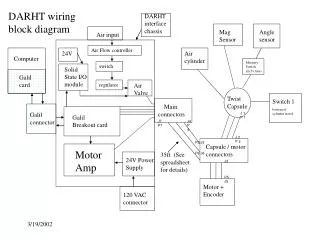
This document provides a detailed wiring block diagram for the DARHT interface chassis, including key components such as the air flow controller, angle sensors, mercury switches, and solid-state I/O modules. It outlines the integration of a 24V air cylinder, various connectors (Galil, motor), and their respective wiring specifications. Additionally, specific attention is given to the regulation of air valves and the connections involved in the setup, including a comprehensive list of parts and a detailed spreadsheet for reference.

Comprehensive Wiring and Sensor Integration for DARHT Interface System
E N D
Presentation Transcript
DARHT wiring block diagram DARHT interface chassis Mag Sensor Angle sensor Air input Air Flow controller 24V Air cylinder Computer Mercury Switch (in 5v line) switch Solid State I/O module Galil card regulator Air Valve Twist Capsule Switch 1 bottom of cylinder travel Main connectors Galil connector J 1 P 1 Galil Breakout card J7 P7 J4 P4 J 2 P 2 P3 J3 Capsule / motor connectors Motor Amp 35ft (See spreadsheet for details) P6 J6 24V Power Supply J3 P5 J5 Motor + Encoder 120 VAC connector