Download
1 / 1
20 likes | 174 Views
University of Rochester Fall 2007 Phy 243W Advanced Experimental Techniques Professor Regina Demina, Sergey Korjenevski, David Starling. Study of the Faraday Effect In the Laboratory Conducted by Andreas Gennis and Jason Robin Presented by Andreas Gennis. What is the Faraday Effect?.

E N D
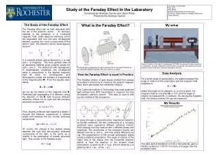
University of Rochester Fall 2007 Phy 243W Advanced Experimental Techniques Professor Regina Demina, Sergey Korjenevski, David Starling Study of the Faraday Effect In the LaboratoryConducted by Andreas Gennis and Jason RobinPresented by Andreas Gennis What is the Faraday Effect? My setup A laser (located on the right) of wavelength 630-680 nm passes through a polarizer (not pictured), through a dielectric located within a solenoid, and traverses one last polarizer before entering a detector (located on the left). The Basis of the Faraday Effect The Faraday effect can be best described with the aid of the dielectric tensor. An isotropic material in the presence of a z-oriented magnetic field, yields diagonal elements which are equivalent and one non-zero off-diagonal element coupling the x and y-components of the electric field. The dielectric tensor would appear as such: ε ε´ 0 ε = -ε´ε 0 0 0 ε In a material without optical absorption, ε is real and ε´ is imaginary. The more general case of an absorbing material gives complex values for both ε and ε´. For dielectrics with diamagnetic or paramagnetic properties, the off-diagonal value is proportional to the applied magnetic field H, while for ferromagnetic and ferrimagnetic media the element is proportional to the magnetization M. From the equality seen below, B = H + 4πM we can lay the blame on the magnetic field B. Polarized light propagating in a dielectric along the direction of the B field receives different refractive indices for its right and left-circularly polarized components. n± = (ε ± iε´)^½ Thus, linearly polarized light passing a length L through the material, experiences a relative phase shift between the two circular polarized components. ∆φ = 2πL (n+ - n-) / λ Of course, the change in the relative phase between the right and left-circularly polarized components of the light, is the same as a rotation in the polarization of linearly polarized light. This rotation is the Faraday angle: θF = ½∆φ Polarized light propagating through a medium and in the same direction as an externally applied magnetic field, will undergo a rotation. Data Analysis For a small range of wavelengths, the relation between the angle of rotation of the polarization and the magnetic field simplifies to: θF = VBL where the length of the dielectric (L, in cm) is given, the magnetic field is controlled (B, in mT), and the angle of rotation is measured (θF, in radians). By varying the magnetic field, the Verdet constant (V) can be measured. How the Faraday Effect is used in Practice The Faraday rotation of radio waves emitted from pulsars is studied in astronomy to measure the galactic magnetic field, which permeates the interstellar medium. The California Institute of Technology has used polarized light emitted from GPS transmitters to measure the total ionospheric electron content. This data is used to edit current models of the ionosphere. My Results The data, with a resistance of 2.68 in the solenoid, gave a Verdet constant of 1.45*10^-4 a factor of 2 larger than the accepted value In going through a perpendicularly magnetized dielectric at normal incidence, the two components of a circularly polarized wave experience different refractive indices. Each emerge from the medium with a different phase and amplitude. The amplitudes of the emergent beams are labeled here by a+ and a–, and their phase difference by ∆φ. The superposition of the circular polarization states produce elliptical polarization. The angle of rotation of the major axis of the ellipse from the horizontal direction (which is here the direction of the incident linear polarization) is given by θF = ½∆φ, and the ellipticity η is given by tan η = (a+ - a-)/(a+ + a-).