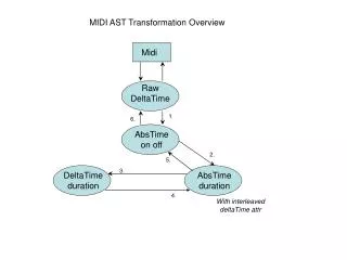
Arduino MIDI Processing
Arduino MIDI Processing. MIDI and OSC. MIDI: is a technical standard that describes a communications protocol , digital interface , and electrical connectors that connect a wide variety of electronic musical instruments , computers , and related music and audio devices.

Arduino MIDI Processing
E N D
Presentation Transcript
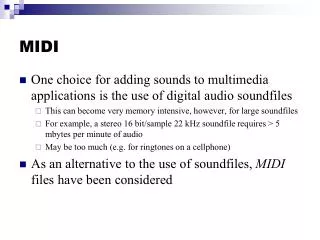
MIDI and OSC • MIDI: is a technical standard that describes a communications protocol, digital interface, and electrical connectors that connect a wide variety of electronic musical instruments, computers, and related music and audio devices. • MIDI carries event messages that specify notation, pitch, velocity, vibrato, panning, and clock signals (which set tempo). For example, a MIDI keyboard or other controller might trigger a sound module to generate sound produced by a keyboard amplifier. • A file format that stores and exchanges the data is also defined. • Advantages of MIDI include small file size, ease of modification and manipulation and a wide choice of electronic instruments and synthesizer or digitally-sampled sounds.
MIDI and OSC • MIDI technology was standardized in 1983. • All official MIDI standards are jointly developed and published by the MIDI Manufacturers AssociationMMA in Los Angeles, and the MIDI Committee of the Association of Musical Electronics Industry (AMEI) in Tokyo. • In 2016, the MMA established the MIDI Association (TMA) to support a global community of people who work, play, or create with MIDI. • https://en.wikipedia.org/wiki/MIDI
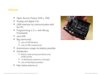
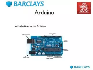
Subjects Covered • Arduino Architecture. • Process of Development of Audio Applications. • Requires Basic knowledge of C language. • Functions • Structures • if statements • for – loops • etc.
Power Supply Arduino Architecture Power Supply & Control • The processor • Communications • User I/O Pins • Power Supply Control • Peripherals Communications Processor Peripherals User I/O - Pins Computer Basic Architecture of Arduino
Arduino Processors • Based on original Atmega x8 processor. • 8 – bit processor • Today we have various architectures that are based on: • 8 – bit • 16 - bit • 32 – bit
Arduino Processors • Variety of processor have different: • Flash memory sizes:Flash memory is used to store the program • Data Sizes:Static Random Access Memory - SRAM • Electrically Erasable Programmable Read Only Memory – EEPROM • Variety of processors support various configurations such as: • 32uX series that supports USB • SAM3X8E ARM Cotrex-M3 – this provides step up in processor technology and power • Arduino Yun that runs Linux with two core processors.
Communications Block • Communicating with the computer is performed over this block. • Typically is a USB/Serial Converter • Some of the chips sets do not have this module and it requires users to provide this function separately if needed.
User I/O Pins • The basic Arduino is capable to being expanded to an almost unlimited number of pins. • The use of the word “pin” to mean a single input/output line is unique to the Arduino and is sometimes confused with a physical pin on a chip. • This in turn has given flexibility to build various Arduino lines where the physical pin assignment is done in software configuration step.
Power Supply Control Block • Power can be provide to Arduino in two ways: • Via USB • Specific power supply. • Modern Arduinos detect automatically the source of the power
Onboard Peripherals • Two kinds of peripherals: • Inside the processor, & • Mounted on the Arduino board.
Peripheral Inside the Processor • The processor peripherals: • Hardware counter/timer • Serial Ports • Pin Interrupts • Analog to Digital (A/D) converter. • For example Timer can be used to: • Produce a fixed frequency pulse Width Modulation (PWM) signal. • Various chips have a variety of number of timers: • From 3 timers that produce 2 pulses each (6 pulses total). • To variety of modes a and timers generating 15 PWMs
Board Peripherals • Arduino Ethernet – has an Ethernet controller. • Arduino WiFi - has an a WiFi module build-in. • In addition to various board peripherals Arduino supports extension boards.
Arduino for Audio • The more powerful the base processor the better and it will make processing easier. • For example: • Shortcomings in terms of peripherals can be accommodated for by adding addional input/output pins using external chips. • This memory however, is not part of the general memory: it can not be used store variables or arrays and it can be used only to store data. • As of 2015 the best Arduino for use in audio projects is Arduino Due: • 96K SRAM • A/D 12 – bit resolution (4096) • 2 D/A
Basic MIDI • Using the MIDI signal • Understanding MIDI messages • Hardware handling of MIDI singles • Building a MIDI shield • Sending and Receiving MIDI messages • USB
Basic MIDI • Using MIDI is the simplest way to get the Arduino to interact with a MIDI supported devices: It is simple to send and receive messages over MIDI interface • MIDI specifies a language of interaction that is understood by an countless number of musical instruments and controllers. • MIDI provides a simple electrical interface and its is designed to be compatible with a wide variety of electronic systems.
What is MIDI? • MIDI – Musical Instrument Digital Interface • Introduced in 1983 with the goal to provide a standardized way to control musical instruments. • MIDI is designed with the goal of generality so that it can be applied to: • Lighting effect • Movement of various automation machinery • Movement of Robots, and more conventionally • For controlling applications involving music.
MIDI • MIDI Standard – defines a protocol • MIDI Standard – defines an interface in terms of voltage, current, and connectors.
Electrical Signals • MIDI is defined as an asynchronous serial interface that uses Speed of communication – 31.250 kHz • Chips that use Universal Asynchronous Receivers and Transmitters (UART), need a clock oscillator that is 16 time the required speed – baud rate. • UART chip has all the logic for sending and receiving and asynchronous data stream. • Arduino chips all have at lest one UART.
Electrical Signals of MIDI • Data is send Asynchronously one bit at a time. • Synchronization of transmitting and receiving streams is done every byte (8 – bits).
Electrical Signals of MIDI • MIDI Uses UART – Universal Asynchronous Receiver and Transmitter protocol. • UART communication requires synchronization step between Receiver and Transmitter. It utilizes 1MHz clock as a base clocking device. This clock then fed into divisor circuit to produce 31.250 kHz signal. • The rate of communication ranges from: • 300 boud • 1200 boud • 9600 bound … • Boud means “data bits per second”
Electrical Signals of MIDI • UART chip has the logic for sending and receiving an asynchronous data stream. • Each Arduino has at least one built in UART. • For example Arduino Mega have four UARTs • Synchronization of Receiver and Transmitter port is done after each byte (8 bits). Stop bit Start bit Data bit 0 Data bit 2 Data bit 4 Data bit 6 Data bit 7 Data bit 3 Data bit 1 Data bit 5
Electrical Signals of MIDI • Optional extra bit that comes bewtween the last data bit and the stop bit – parity bit. • Parity bit if used will be chosen so that there is an odd or even number of data bits. • Note that in MIDI signaling parity bit is not used. • There a number of options is UART communications: • 5,7, or 8 bits • Odd , Even or no parity, • 1, 1 *1/2 or 2 stop bits
Electrical Signals of MIDI • For MIDI communication requires 0 stop bits to be send, and 8 bits of data to be transmitted.
MIDI Messages • In order to control a MIDI device, several bytes are combined to form a MIDI message. • The number of bytes required varies based on the content of the message. • There are a number of classes of MIDI messages to control various aspects of music system. • Each MIDI connection can communicate with its MIDID channels. Each MIDI device can be set to be one or several different MIDI channels. • Typically there are some switches on the device that control which channel it is on.
MIDI Messages • The channel number is embedded in the first byte of the MIDI message as the four least significant bits. • Message's first byte contains two pieces of information: • The channel number, what kind of message it is. • How many other bytes make the whole message • The first by of MID message is often called the “status byte”. • In the case of the note, there are tow other bytes associated with this message as displayed next.
MIDI Messages • The anatomy of a note on message
MIDI Messages • First MIDI message has the most significant bit set. • All subsequent messages start with most significant bit set to zero.
MIDI Messages • The two other bytes in the MIDI message contain • the note numbed • and the velocity (or how hard the note is struck) • Because the first most significant bit is reserved for message only, the range of values contained in the message is 0-127. • Because this is insufficient in order to generate all the notes: • Note’s timber is another ‘quality’ of sound that is required to be set for some instruments. • Sound color of piano changes depending on how hard you hit the key.
‘Note on’ and ‘Note off’ • ‘Note on’ message is almost always accompanied by a matching ‘Note off’ message. • We sow in previous slides how the details of ‘Note on’ message. • The MIDI system allowas two ways of turning a note off. • It’s own note off message, with data being the note number and the velocity being how quickly it was released. • Some devices may ignore this value while other ones may set it to a fixed value typically set to 0. • Turning a note off message by seinding a note on message with note on velocity set to 0.
‘Note on’ and ‘Note off’ • Any system receiving MID should be capable of coping with both methods of running a note off. • If there is not a note off message that matches a previous note on message, a note can become stuck.
There are several different binary number representational conventions for signed and unsigned numbers. Most notable are: • . Hexadecimal Notation • Sign Magnitude • One’s Complement • Two’s Complement Example of 4-bit signed numbers is presented in the Table for three formats listed above: Example Table of 4 bit number representations
MIDI Connections • There are 3 types of MIDI sockets on the device: • IN • OUT • THRU • When connecting different devices, a MIDI OUT must be connected to a MIDI IN. • MDI THRU is a copy of the single on the MIDI IN and can be used chin one MIDI OUT to several device:
Arduino Implementation of MIDI • Arduino has a UART built in. • It uses it to upload music and send and receive serial data. • By setting appropriate serial interface to the correct bound rate, one can • Send to, • Listen to, any standard MIDI device.
Software MIDI Output • Driving MIDI is done through a C program described next: /* Generating MIDI output * Sending MIDI serial data, automatically for a test */ # define midiChannel (byte) 0 // Channel #1 void setup() { // Setting up Serial Port (UART) Serial.begin(31250); // MIDI Speed } void loop() { intval; val = random(20, 100); noteSend(0x90, val, 127); // note on delay(200); noteSend(0x80, val, 127); //note off delay(800); } // playing a MIDI note void noteSend(char cmd, char data1, char data2) { cmd = cmd | char(midiChannel); // merge channel number Serial.write(cmd); Serial.write(data1); Serial.write(data2); }
Software MIDI Input /* MIDI Input * Listen for MIDI Serial Port */ byte channel = 1; // MIDI channel - #2 void setup() { pinMode(13, OUTPUT); // LED to light up digitalWrite(13, LOW); // Turn LED off Serial.begin(31250); // start serial port } void loop () { checkIn(); // input arrivals } void checkIn() { static int state = 0; // 0 – command waiting // 1 – note waiting // 2 – velocity waiting static char note = 60; static Boolean noteDown = LOW;
if (Serial.avialble() > 0) { byte icommingByte = Serial.read(); switch (state) { case 0: // status-byte, note on if (incommingByte == ( 0x90 | channel)) { noteDown = HIGH; state = 1; } // status-byte, note off if (incommingByte == ( 0x80 | channel)) { noteDown = LOW; state = 1; } // status-byte, note on if (incommingByte == ( 0x90 | channel)) { noteDown = HIGH; state = 1; }
case 1: // note to play or stop if (incommingByte < 128) { note = incommingByte; state = 2; } else { state = 0 } break; case 2: if (incommingByte < 128) { doNote(note, incommingByte, noteDown); } state = 0; // reset state machine } } }
Software MIDI Input void doNote(byte note, byte velocity, boolean down) { // if velocity = 0 on a ‘Note ON’ command, treat it as a note off if ((down == HIGH) && 9velocity == 0)) { down = LOW); } // doing something with a note message // toggling Pin 13 and ignoring the note value and velocity digitalWrite(13, down); }
Additional Notes on MIDI • We have seen previously the implementation on NOTE ON and NOTE OFF messages. • They are going to be essential in playing the notes (sounds). • MIDI controller is a device that can control an aspect of a sound: • Volume, • Vibrato, • Position of the instrument on a stage, etc. • Two types of messages: • A channel message aimed a one playing channel, and • A system message aimed at the whole system.
Additional Notes on MIDI • There are 5 types of channel messages related to voice. • Note on/Note off • Controller change • Program Change • Pitch bend • Aftertouch
Additional Notes on MIDI • We already have discussed note on/note off messages. • For full specification of MIDI see this web site:http://www.midi.org/techspecs/
Controller Change MIDI Messages • A method for providing a control change. • Up to 120 controllers on each MIDI channel. • Associated with each channel is a number with a value between 0 – 127. • Controller channel usages: • ON/OFF switching, etc. 1 0 1 1 0 0 1 0 Top bit set means this is a message number Message Channel Value = 11 = 0xB Controller Change Value = 2 = 0x2 Chanel 3