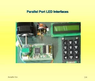
Parallel Port LED Interfaces
Parallel Port LED Interfaces. Output LEDs. Output LEDs. Direct Interface : 각 Output Pin 에 하나의 LED 을 접속 한다 . Scanned Interface : LED 는 Matrix 구조로 배치된다 . Multiplexed Interface : Multiplexing Hardware 사용 하여 Scanned Interface 보다 더 많은 LED 를 배치 할 수 있다. Single LED Interface.

Parallel Port LED Interfaces
E N D
Presentation Transcript
Output LEDs • Direct Interface : 각 Output Pin에 하나의 LED 을 접속 한다. • Scanned Interface : LED 는 Matrix 구조로 배치된다. • Multiplexed Interface : MultiplexingHardware 사용 하여 Scanned Interface 보다 더 많은 LED 를 배치 할 수 있다.
Single LED Interface • Open Collector 를 이용한 LED 제어
8.2.1 Single LED Interface • LED의 전류를 제어 하는 대표적인 방법
Single LED Interface Id = 10mA, Vd = 2V
8.2.1 Single LED Interface Id = (Vcc – Vd – Vce) / R R = (Vcc – Vd – Vce) /Id
8.2.3 Scanned Seven-Segment LED Interface • LED의 동작 점이 10mA, 2V 이고, • 3개의 LED를 스캔 하는 경우 • 각 LED의 Duty는 33% 가 된기 때문에 • Active 되는 LED 의 동작 전류는 30mA 가 되어야 한다.
C software interface of a scanned LED display. // MC68HC812A4 // PB7-PB0 output, 7 bit pattern // PC2-PC0 output, selects LED digit unsigned char code[3]; // binary codes static unsigned char select[3]={4,2,1}; unsigned int index; // 0,1,2 #define C5F 0x20 #pragma interrupt_handler TOC5handler() void TOC5handler(void){ TFLG1=C5F; // Acknowledge TC5=TOC5+10000; // every 5 ms PORTC=select[index]; // which LED? PORTB=code[index]; // enable if(++index==3) index=0;} void ritual(void) { asm(" sei"); // make atomic index=0; DDRC=0xFF; // outputs 7 segment code DDRB=0xFF; // outputs select LED TMSK1|=C5F; // Arm OC5 TIOS|=C5F; // enable OC5 TSCR|=0x80; // enable TMSK2=0x32; // 500 ns clock TC5=TCNT+10000; asm(" cli"); }
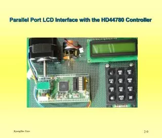
Scanned LED Interface Using the 7447 Seven-Segment Decoder Seven-Segment Decoder
C software interface of a multiplexed LED display. // MC9S12C32, CodeWarrior C unsigned short Global; // 12-bit packed BCD const struct LED { unsigned char enable; // select unsigned char shift; // bits to shift const struct LED *Next; }; // Link typedef const struct LED LEDType; typedef LEDType * LEDPtr; LEDType LEDTab[3]={ { 0x04, 8, &LEDTab[1] }, // Most sig { 0x02, 4, &LEDTab[2] }, { 0x01, 0, &LEDTab[0] }}; // least sig LEDPtr Pt; // Points to current digit void interrupt 13 TC5handler(void){ TFLG1 = 0x20; // Acknowledge TC5 = TC5+10000; // every 5 ms PTT = (Pt->enable) +(Global>>(pt->shift))<<4); // BCD Unpacking and // BCD code -> PT4 -> PT7 Pt = Pt->Next; } void LED_Init(void) { asm sei // make atomic DDRT = 0xFF; // outputs to LED's Global = 0; Pt=&LEDTab[0]; TIE |= 0x20; // Arm OC5 TIOS |= 0x20; // enable OC5 TSCR1 = 0x80; // enable TSCR2 = 0x01; // 500 ns clock TC5 = TCNT+10000; asm cli }
Integrated LED Interface Using the MC14489 Display Driver • MC14489 Display Driver를 이용할 경우의 장점 • Chip Count 가 감소한다. • Scanning Function 이 hardware 적으로 수행된다. • MC14489를 Cascade 하게 구성하여 큰 규모의 Display 장치를 용이 하게 구현 할 수 있다.
Integrated LED Interface Using the MC14489 Display Driver Packed BCD를 이용한 24Bit Data 전송 예 5 Digit Packed BCD Decimal Point Control
C software interface of an integrated LED display. // MC68HC812A4 // PS5/MOSI = MC14489 DATA IN // PS6/SCLK = MC14489 CLOCK IN // PS7 (simple output) = MC14489 ENABLE void ritual(void) { DDRS |= 0xE0; // outputs to MC14489 SP0CR1=0x50; // bit meaning // 7 SPIE=0 no interrupts // 6 SPE=1 SPI enable // 5 SWOM=0 regular outputs // 4 MSTR=1 master // 3 CPOL=0 match timing with MC14489 // 2 CPHA=0 // 1 SSOE=0 PS7 is simple output // 0 LSBF=0 MSB first SP0CR2=0x00; // no pull-up, regular drive SP0BR=0x02; // 1Mhz SCLK PORTS|= 0x80; // ENABLE=1 PORTS&= 0x7F; // ENABLE=0 SP0DR= 0x01; // hex format while(SP0SR&0x80)==0){}; PORTS|=0x80;} // ENABLE=1 void LEDout(unsigned char data[3]){ //packed PORTS &= 0x7F; // ENABLE=0 SP0DR = data[2]; // send MSbyte while(SP0SR&0x80)==0){}; SP0DR = data[1]; // send middle byte while(SP0SR&0x80)==0){}; SP0DR = data[0]; // send LSbyte while(SP0SR&0x80)==0){}; PORTS |= 0x80;} // ENABLE=1