Download
1 / 84
850 likes | 1.03k Views
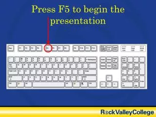
Building Electronic Circuits Mr. Clarvis Press F5. Main Menu. Welcome to the electronics tutorial Please select one of the above options to proceed For information on how to use this resource click on RESOURCE GUIDE

E N D
Main Menu • Welcome to the electronics tutorial • Please select one of the above options to proceed • For information on how to use this resource click on RESOURCE GUIDE • To learn about common electronic components and how to identify them click on COMPONENTS • To learn how to solder correctly click on SOLDERING GUIDE • For a glossary of all of the terms found in this resource click on GLOSSARY • To test your knowledge, click on TEST ME!
Guide to using this resource Click on the silver link buttons to navigate around the resource Click on the BACK button to take you to the previous page Click on any image highlighted by an indigo border for more in depth information
Component Identification This page allows you to identify common components. If you know the name of the component click on the appropriate button. If you only know what the component looks like click on the picture.
Resistors A resistor is a component that limits the flow of current through an electronic circuit. The property of a resistors is known as it’s resistance, measured in Ohms. A low value resistor will conduct more current than a high value resistor. Resistor values are identified by a number of coloured stripes that are painted on the body. Resistor schematic symbol A common resistor found in electronic circuits is show here. The coloured bands tell us the resistance value of the resistor. To find out how we do this click on the picture.
Resistor Colour Codes Most resistors have four or five coloured bands to identify them. To decipher the code we use the colour code chart shown. To make things easier, when we get a value of 1000 Ohms we call it 1K (1 Kilo Ohm) and when we get a value of 1,000,000 Ohms we call it 1M (1 Mega Ohms) The tolerance of the resistor is the accuracy of the stated resistance value. A resistor with a gold band Could have a resistance +5% or –5% of that of what it should be. So resistors are not accurate!
Capacitors A capacitor is a component that is capable of storing electrical charge. The property of a capacitor is known as its capacitance, this is measured in Farads (F). A capacitor with a higher capacitance is capable of storing more electricity. There are a variety of types of capacitor, all of which look slightly different. Capacitor schematic symbol Polyester Capacitor Ceramic Capacitor Polarised capacitor symbol Some capacitors are polarised, which means they must be connected the correct way round. If you don’t they are likely to explode! Electrolytic capacitors are polarised, the negative terminal is indicated by a white stripe on that side of the body. Electrolytic Capacitor
Diodes A diode is a component that allows current to flow in only one direction only, just like a one way valve. A diode only has two leads: an Anode and a Cathode. Current can only flow from the anode to the cathode, not the other way around. Diodes are used for directing electricity around a circuit in the desired direction. ANODE CATHODE ANODE CATHODE Stripe identifies cathode
Transistors COLLECTOR • A transistor can be used to amplify or switch larger currents under the control of a small current. • A transistor is a component with three terminals: • Base • Collector • Emitter • The current flowing between the collector and emitter is controlled by the current flowing into the base. • Transistor models are identified by a model number printed on the body. BASE EMITTER
Integrated Circuits (Chips) An integrated circuit is a whole circuit that has been constructed on a tiny piece of silicon. Common chips used in school contain up to a hundred components. Computer chips on the other hand contain hundreds of millions of components! Cut-away diagram of an chip A silicon wafer containing many silicon chips before they have been separated and packaged.
Light Emitting Diodes (LEDs) An LED is a diode that emits light when current flows though it. An LED only has two leads: an Anode and a Cathode, the same as a normal diode. Current can only flow from the anode to the cathode, not the other way around. The diode must be connected the right way round or it will be damaged. Also the current allowed to flow through the device must be limited with a resistor.c ANODE CATHODE Lens ANODE CATHODE (Short leg)
Push to Make Switch is usually off until the button is pressed. Returns to off position once released. Single Pole Single Throw (SPST) Depending on the position of the switch, it is either on or off. Single Pole Double Throw (SPDT) Also known as a change over switch. Depending on the position of the switch the central contact is connected to either the top or bottom terminal Push to Break Switch is usually on until the button is pressed. Returns to on position once released. Double Pole Single Throw (DPST) This is just like two SPST switches connected to the same switch. They are commonly used for switching off power to mains equipment. Double Pole Double Throw (DPDT) This is just like two SPDT switches operated by the same switch. Switches
Relays A relay consists of an electromagnet (a coil of wire), and a switch. When the coil is energised the switch contact is attracted to the electromagnet and the switch changes position. The relay allows very large currents or voltages to be safely controlled by low power circuits. Schematic symbol of a relay. The box represents the coil For this particular relay: The switch is usually in the NC position (Normally closed) When the coil is energised the switch moves into the NO position (Normally open) When the coil is de-energised the coil returns to the NC position
Glossary Capacitor A component that stores electricity. Circuit Board See PCB. De-soldering Braid A copper braid which is laid on top of a heated joint to remove solder when heated. De-soldering tool A tool, usually with a plunger, used to remove solder from joints. Diode A component that allows current to flow in one direction only. Dry Joint A faulty solder joint due to dirt on contacts or the application of insufficient solder. ESD ESD stands for Electrostatic Discharge. It is the discharge of static electricity that can cause damage to certain electronic components such as transistors and silicon chips. IC IC stands for Integrated Circuit and is the correct name for a silicon chip. Joint The connection between two or more metal parts with solder. LED Light Emitting Diode. A device that emits light when current flows through it. Pad A pad is the part of a PCB with a hole drilled in where component leads or wires are soldered. PCB Printed Circuit Board. A board usually made of fibreglass or epoxy bonded paper with copper tracks etched on one or both sides. Relay An electromechanical device for switching large currents with a small one. Resistor A component that limits the flow of electrical current. Solder The metal used during soldering. Soldering The process used to join metal components. Switch A mechanical device for interrupting the flow of electricity. Track The copper conductors that run on one or both sides of the PCB. Transistor A component that can amplify or switch electrical currents. Wire cutters A tool used for trimming component leads and wires. Wire strippers A tool used for removing the outer insulating layer of wire.
Soldering Soldering is a method of joining two pieces of metal together using a molten metal. To learn more about soldering, click on any of the topics shown:
Health & Safety • Soldering is not dangerous provided you follow these simple rules: • Soldering irons get VERY hot and can cause severe burns. Make sure you handle it with care and always put the iron back in the stand when you are not using it. If you burn your hand run it under the cold tap for ten minutes & see a first-aider. • Solder usually contains a mixture of Lead, Tin and a core of resin. When the solder is heated the smoke that comes off is harmful. Make sure you work in a well ventilated area and use any fume extraction that may be available. • Wear goggles. These will protect your eyes from any small pieces of wire that may fly off as you snip them with the wire cutters. • Most soldering irons run directly from the mains. Take great care that you do not burn the flex as you could electrocute yourself or someone who uses the iron after you. • Never flick solder off the tip of the iron, to clean it rub it on the moistened sponge.
Basic Equipment • In order to make a good job of any task it is important to have the correct tools. • The basic tools you will need are: • Soldering Iron • Soldering Iron Stand • Wire Cutters • Wire Strippers • long Nose Pliers • Solder • Click on any of the highlighted tools to learn more about them
De-soldering Equipment Pressing the plunger compresses a spring inside the de-soldering tool. Pressing the button releases the spring and causes air to be quickly sucked up the nozzle. A de-soldering tool, is a tool that is used for sucking up molten solder from a joint where a component is to be removed. Nozzle. Sucks up molten solder when the button is depressed. Solder wick is a copper braid which is laid on top of a heated joint to remove solder when heated. This can be quite useful when lots of solder has to be removed at the same time, such as when solder has spilled between a number of tracks on the PCB
De-soldering • Push the plunger all the way in until it locks in place. • Heat up the joint to be de-soldered with your iron until the solder melts. • Hold the nozzle of the de-soldering tool over the joint and press the button. • The molten solder will be sucked up into the de-soldering tool. • 5. Re-prime the tool by pushing in the plunger (this will also force out any solder that has set inside. • Repeat for the other leads of the component. • Use a pair of long nose pliers to gently tease out the component to be removed. You may need to apply a little heat to the joints to free them up.
Soldering Guide By following these simply steps you should be able to create a perfect soldered joint. Click on any image for more information: 5. Heat up the joint by applying the tip of the soldering to the joint 1. Ensure that the PCB is clean 6. Apply solder to the joint until solder runs all around the PCB pad and component leg 2. Clean the tip of the soldering iron on the moist sponge 3. Push the component legs through the PCB and bend the legs outwards slightly 7. Remove the solder and then the soldering iron. You should be left with a good quality joint 8. Clean the tip on the sponge before going onto the next joint 4. Snip off the legs of the component leaving about 2mm
Soldering GuideCleaning the PCB Because the tracks on printed circuit boards are made out of Copper they are easily tarnished in the air. If the board looks dull then it must be polished or a good quality joint can not be achieved. Rubbing the tracks with a polishing block, as shown here will remove the tarnished layer and any grease that may have built up on the board. Freshly polished copper is shiny and pink in colour Mass produced circuit boards are usually varnished to protect the copper underneath. This type of circuit usually look green on the copper side.
Soldering GuideCleaning the soldering iron Once solder has been melted by the soldering iron the tip will start to develop a layer of oxidised metal and residues of burnt flux from the solder. If the soldering iron tip is not cleaned regularly a very poor joint will be achieved. A piece of damp silicone sponge is used to wipe off any debris. The sponge must be kept damp otherwise it will get burned by the soldering iron. Ideally the tip of the iron should be wiped after every joint or when it starts to look dull.
Soldering GuideComponent placement The leads of the components are bent outwards slightly to prevent the component from dropping out when the circuit board is turned upside down to apply the solder. Do not bend the legs right over it will make it very difficult to remove the component at a later date should it be faulty. Also the joints will look very messy and you run the risk of shorting the components together.
Soldering GuideTrimming the component legs Wire cutters are used to snip the leads or wires. It is important to make sure that the lead is pointing away from you as you cut as pieces of wire can fly off when being snipped.
Soldering GuideHeating the joint Apply heat to the joint you wish to solder before applying any solder. You must never apply solder to the soldering iron and attempt to transfer this to the joint as this will result in a very poor joint. It is important to remember when heating the joint that some components, such as Transistors, Diodes and Integrated Circuits are easily damaged by excessive heat. It is therefore important to make sure that you do not linger with the soldering iron on the leads of these components. Another thing to remember is that the longer you heat the copper track up, the more likely it is to become unattached from the board.
Soldering GuideSoldering the joint After a few seconds of applying heat from the soldering iron the solder should be fed slowly onto the joint. Because the metals are hot the solder will melt onto them. Hold the soldering iron and solder in place until the solder flows nicely around the component lead and copper pad. First remove the solder and then the soldering iron. Do this the other way round and you could end up with you solder wire stuck on your circuit board! The picture on the right shows a good quality joint.
Soldering GuideWhat the joint should look like The diagram below shows a cross-section of a lead soldered onto a copper track. It can be seen that the solder has flowed all around the lead and track evenly and produced a good electrical and mechanical joint. Copper pad Solder PCB Component lead or wire
Bad Joints These diagrams show cross sections of poor quality soldered joints. Click on an image for more information A perfect joint Not enough solder Too much solder Dirty circuit board
Bad JointsNot enough solder Not enough solder means that there isn’t enough solder to form the joint. This is called a dry joint. Just enough solder has been used for this joint and it can be seen how the solder has flowed nicely around the component lead and PCB pad.
Bad jointsToo much solder Too much solder leads to blobs of solder on the joint. There is the risk of such joints running into one another during soldering. Just enough solder has been used for this joint and it can be seen how the solder has flowed nicely around the component lead and PCB pad.
Bad JointsDirty joints This example shows an attempt to solder onto dirty contacts. It can be seen how the solder has not flowed around the wire. Here it can be seen that the joint has not been heated up long enough and therefore the solder has not been able to flow onto the terminal. This could also be caused by a dirty contact. Just enough solder has been used for this joint and it can be seen how the solder has flowed nicely around the component lead and PCB pad.
Component Care • When building electronic circuits there are three main factors that can result in damage to components: • Mechanical stress • Thermal stress (Getting the components too hot) • Electrostatic Discharge (ESD) • To find out more click on the buttons below:
Mechanical Stress Because most components are quite small and delicate they are easily damaged by mechanical stresses. These are simply avoided by handling the components with care and not bending the component legs too close to the body where they are more likely to snap off.
Thermal Stress • Some components are damaged by excessive heat. The components that are easily damaged are: • Transistors • Diodes • LEDs (Light Emitting Diodes) • Integrated Circuits (Chips) • To avoid damage it is important not to get the components too hot by leaving the soldering iron on the leads for too long. • A device called a heat sink can be clipped onto the component the helps to drain the heat away from the component. A crocodile clip can also be used if clamped onto the legs of the component.
Electrostatic Discharge (ESD) • Did you know that in every day life your body can get charged up with electricity to the order of a few thousand volts? • As your clothes rub against you, and your shoes against the floor you become charged up with static electricity. When you touch a metal object electricity is discharged from you into the metal object. • If you discharge this electricity into certain components then they will be damaged. Some such components are: • Some Transistors (CMOS types) • Some Integrated Circuits (for example the 4000 series of CMOS chips) • Blue and White LEDs • It is possible to protect against ESD, to find out how click on the button below:
ESD Protection In industry, technicians involved in soldering ESD susceptible components wear special wrist bands that conduct any static electricity away to earth. They may also work on special conductive mats and desks. In the classroom though there are a few simple precautions that can help to prevent damage to components: • Before touching a sensitive component discharge any static electricity by touching a metal object such as a radiator. • Avoid touching the leads of the component, handle the component by the plastic areas. Static preventing wrist strap Special plastic bags for storing sensitive components
Soldering Iron Stand Soldering irons get very hot when in use. The tip of the iron gets to a temperature of over 300oC and therefore must be kept safely away from furniture and your hands. Heavy base Silicone sponge A soldering iron stand holds the iron while it is switched on but not in use. When soldering, the tip of the iron will become dirty and must be kept clean. When moistened, the yellow sponge can be used to clean the tip of the iron to ensure that good quality joints are made.
Soldering Iron Mains flex. Should be made of silicone to help prevent it from being damaged by accidental burning Replaceable soldering iron tip Handle A soldering iron consists of a handle, an electric heating element and a metal tip. When the iron is switched on the tip gets to a temperature sufficient to melt solder. For general electronics work the iron should have a power rating of between 15 and 25 Watts. It should be fitted with a chisel shaped tip of around 2mm.
Wire Cutters Insulated handles Pivot Sharp cutting edge
Wire Strippers Insulating handles Pivot When the handles are squeezed the pincers grip the insulation and strip it off the wire
Long Nose Pliers Cutting edge for cutting wire Insulating handles Gripping edge
Solder Solder is a metal that is used for joining pieces of metal or wire together. When heated sufficiently solder will melt and turn into a liquid. It can be then used to act as a kind of “glue” to stick two pieces of metal together. Solder for electronics work is usually an alloy of Lead and Tin. This alloy has the properties of having a low melting point as well as being a good conductor of electricity. Electronics solder also has a core of flux running though it. This is a type of resin that melts with the solder and aids its flow onto the joint. Without it the solder would simply stick to the soldering iron in a blob.
Test Me! So now is the time to test yourself to see how much you’ve learnt! Select from one of the below topics to test your knowledge:
Component IdentificationQuestion 1 Which component is represented by the symbol shown below? Click on the picture of the component you think Resistor Capacitor Diode
Component IdentificationQuestion 1 – CORRECT! You have correctly identified the component! Resistor
Component IdentificationQuestion 1 - INCORRECT You identified the symbol as a Capacitor You can have another chance at the question Here's a clue: The schematic symbol is very similar in shape to the actual component
Component IdentificationQuestion 1 - INCORRECT You identified the symbol as a Diode You can have another chance at the question Here's a clue: The schematic symbol is very similar in shape to the actual component but it doesn't matter which way round it is connected
Component IdentificationQuestion 2 Which component is represented by the symbol shown below? Click on the picture of the component you think Electrolytic Capacitor Ceramic Capacitor Relay
Component IdentificationQuestion 2 - CORRECT! You have correctly identified the component! Electrolytic Capacitor
Component IdentificationQuestion 2 - INCORRECT You identified the symbol as a Ceramic Capacitor You can have another chance at the question Here's a clue: You are close, just remember that particular component you chose is non-polarised (ie. it doesn't matter which way you connect it)