Download
1 / 10
100 likes | 200 Views
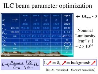
RF system issues due to pulsed beam in ILC DR. S. Belomestnykh Cornell University. RF system parameters. Main constrains 10 Hz beam repetition rate, 50 ms beam on/off time, ~ 1 ms injection/extraction time to fill/empty the ring Available klystron power: 1 MW or 250 kW per cavity

E N D
RF system issues due to pulsed beam in ILC DR S. Belomestnykh Cornell University Belomestnykh, RF for pulsed beam ILC DR, IWLC2010
RF system parameters Main constrains 10 Hz beam repetition rate, 50 ms beam on/off time, ~1ms injection/extraction time to fill/empty the ring Available klystron power: 1 MW or 250 kW per cavity RF window power handling Belomestnykh, RF for pulsed beam ILC DR, IWLC2010
The RF power in the presence of beam can be expressed as RF power demand (1) where b >> 1 is the coupling factor, QL is the cavity loaded quality factor, 0 is the beam phase relative to the crest of RF wave (a.k.a. synchronous phase), y is the cavity tuning angle. The first term includes active part of beam loading (due to particle energy loss), the second term includes reactive beam loading. The latter is usually compensated by appropriate cavity detuning with a mechanical tuner so that the second term in square brackets is always zero. And then for maximum beam current and optimal quality factor the power demand is simply equal to the beam power per cavity (194 kW). Belomestnykh, RF for pulsed beam ILC DR, IWLC2010
RF power demand (2) However, it is not possible to tune the cavity mechanically fast enough to compensate reactive portion of the beam loading during injection (~1ms). For the DR parameters we get And, assuming that the cavity is appropriately detuned to compensate the beam current, the power demand when the beam is ejected becomes which (i) exceeds the power available from the klystron and (ii) being fully reflected from the cavity, creates standing wave pattern thus creating a power handling problem for an RF window/coupler and transmission line. Below we present several approaches on how to deal with this problem and what additional studies are necessary. Belomestnykh, RF for pulsed beam ILC DR, IWLC2010
Alessandro Gallo (DAFNE RF system, LNF) performed further analysis and derived Option #1: lower overvoltage factor where h is the overvoltage factor. One can see that for h ≤ 2 the cavities can be operated at fixed detuning while the power demand for zero beam current does not exceed the maximum beam power. Questions: • Is it possible to reduce the overvoltage factor? • How it was chosen in the first place? Belomestnykh, RF for pulsed beam ILC DR, IWLC2010
This is also due to Alessandro Gallo’s analysis. For an arbitrary detuning one can derive Option #2: optimal detuning For h > 2 the cavities can be operated at an optimal detuning that is different from maximum detuning and is derived from a condition PFWD(0) = PFWD(Ibmax): The power demand increase factor is Belomestnykh, RF for pulsed beam ILC DR, IWLC2010
No we can compare maximum detuning case with optimal detuning Option #2: optimal detuning (2) • For the DR parameters tanyopt = 1.864 andpower demand is 217kW. Concern: • The RF system will have to operate half of the time on a wrong side of the resonance, where it is unstable (the first Robinson criterion). 50 ms is long enough time for the instability to develop. A direct RF feedback around the cavity may help, but a careful study and simulations are required to determine if it is possible to develop such a feedback for the ILC DR case. Belomestnykh, RF for pulsed beam ILC DR, IWLC2010
With a fast frequency tuner (piezoelectric or magnetostrictive) one can detune the cavity fast enough to follow the beam current increase during injection/extraction. The only known to me storage ring, where piezo tuner were used in routine operation on superconducting cavities, is TRISTAN. I don’t have the parameters of that system though. CESR B-cell cryomodules are equipped with piezo tuners, which were used in experiments to study microphonic noise and feedback, but the piezos were not intended to cover large detuning and hence the range is limited: Option #3: fast frequency tuner Further studies/concerns: • This approach will need further studies of achievable tuning range and speed. • Tuning in ~1ms is within the technology state of the art • But excitation of mechanical resonances could be a limiting factor. • Alternative tuning schemes (reactive coupling?) Belomestnykh, RF for pulsed beam ILC DR, IWLC2010
Accepted for publication in PRST-AB • This would involve developing a fast waveguide tuner to change the cavity coupling during injection/extraction and thus decrease the power demand. Such tuners are under development at several laboratories, but are not used in operations yet. Changing the cavity coupling alone is not enough as even in the best case of • Qext = f / (2·|Dfmax|) = 4.01×10⁴ (maximum detuning, no beam) • the power demand is still high: • Pforw = |tany|·Pb = 248 kW. • It may, however be used in combination with options #2 or #3. Option #4: fast coupling change Further studies: • This approach will need further studies of achievable coupling range, speed and power handling. Belomestnykh, RF for pulsed beam ILC DR, IWLC2010
10 Hz operation of the ILC Damping Ring RF system seems to be feasible. • We have presented four different options. Each of them however have challenges. • Option #3 is the most attractive as the RF power demand is minimal under it. However, it requires extensive R&D. • Option #1 would be the most easily implementable is the overvoltage factor can be lowered to 2. Common concerns & studies needed (in addition to those listed for individual options): • RF window/coupler power handling with full reflection (except option #3) • Feedforward to mitigate transients during beam injection/extraction • Pulsed operation of the RF system is worth considering as it will save power and reduce thermal load on RF window/coupler. Two options here: (i) pulsed RF and klystron mod anode; (ii) pulsed klystron HV. Summary Belomestnykh, RF for pulsed beam ILC DR, IWLC2010