Download
1 / 21
220 likes | 371 Views
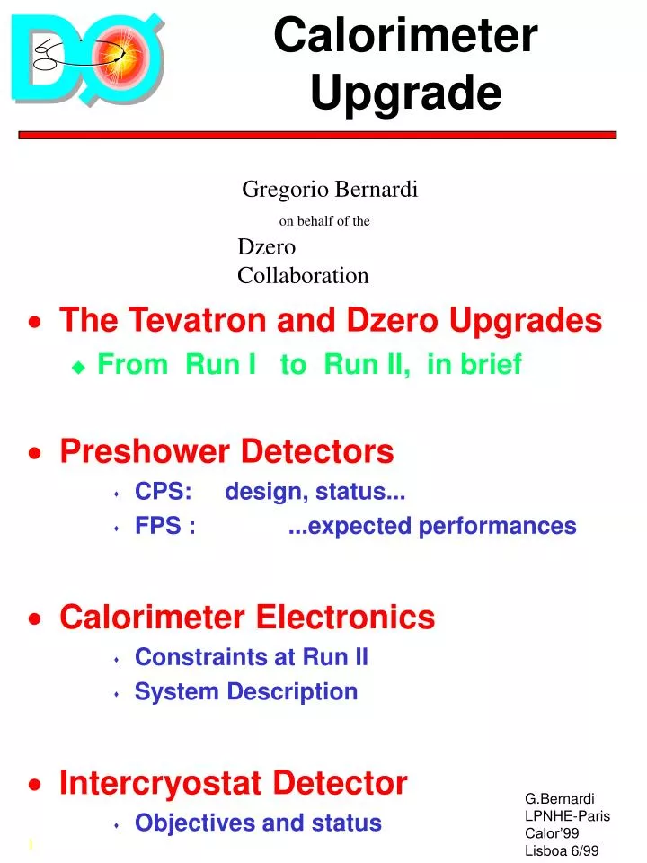
Calorimeter Upgrade. The Tevatron and Dzero Upgrades From Run I to Run II, in brief Preshower Detectors CPS: design, status... FPS : ...expected performances Calorimeter Electronics Constraints at Run II System Description Intercryostat Detector

E N D
Calorimeter Upgrade • The Tevatron and Dzero Upgrades • From Run I to Run II, in brief • Preshower Detectors • CPS: design, status... • FPS : ...expected performances • Calorimeter Electronics • Constraints at Run II • System Description • Intercryostat Detector • Objectives and status Gregorio Bernardi on behalf of the Dzero Collaboration
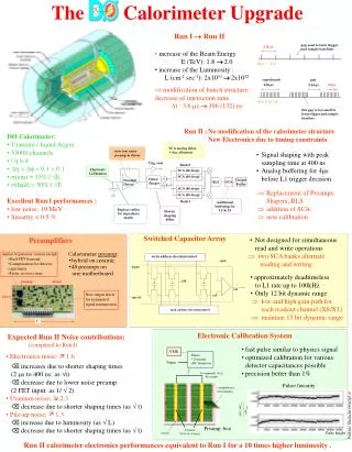
Timings • Bunch structure gap used to form trigger and sample baselines 3.56us Run I 6x6 superbunch gap 4.36us 2.64us 396ns Run II 36x36 this gap is too small to form trigger and sample baseline • We expect the bunch structure to evolve to a minimum 132 ns between bunches - design to that • We expect 3 gaps, gap size must be a multiple of 132ns (7 RF buckets)
Experiment • Physics program at Run II (driven by high pT physics) • Searches for phenomena beyond the SM • Top quark studies • Electroweak measurements • QCD tests • B physics • Accelerator environment implies: • Fast electronics, pipeline • Sophisticated trigger systems • Radiation hard detector components
E.M. Calibration • Use J/Psi , Upsilon , Z
Forward Scintillator + New Electronics, Trig, DAQ Central Scintillator New Solenoid, Tracking System SMT, SciFi,Preshowers Forward Mini-drift chambers Shielding DÆ Upgrade
Tracking System Fiber Tracker Silicon Microstrip Tracker Forward Preshower Solenoid Central Preshower
Central Preshower • Central Preshower already mounted on the solenoid • Scintillator + Lead • Performances studied with MC and cosmic rays
Central Preshower • Simulation results: • Good spatial resolution • Preshower recovers resolution.
Forward Preshower • Azimuthal wedges (u,v) scintillator/lead with • readout via fibers side view
Fwd Preshower • Azimuthal Wedges ready • Test beam results
Fwd Preshower • Test Beam Results (FNAL ‘97)
Calorimeter Electronics • Objectives: • Accommodate reduced minimum bunch spacing from 3.5 us to 396 or 132 ns • Storage of analog signal for 4us for L1 trigger formation • Generate trigger signals for calorimeter L1 trigger • Maintain present level of noise performance and pile-up performance • Means • Replace preamplifiers • Replace shapers • Add analog storage • Replace Calibration System
Calorimeter Electronics 55K readout channels • Replacement of Preamps, Shapers, BLS, addition of SCA, new calibration. SCA analog delay >4usec, alternate new low noise preamp & driver Trig. sum Bank 0 SCA (48 deep) SCA (48 deep) x1 Filter/ Shaper Output Buffer Preamp/ Driver SCA BLS Detc. x8 SCA (48 deep) SCA (48 deep) Bank 1 Additional buffering for L2 & L3 Replace cables for impedance match Shorter shaping 400ns
preamp driver New calorimeter preamp, hybrid on ceramic. Forty eight preamps on a single motherboard FET 2” Preamplifier • similar to previous version except • Dual FET frontend • Compensation for detector capacitance • Faster recovery time New output driver for terminated signal transmission
write address decoder/control reset input ..x48.. out ref cap ref read address decoder/control SCA • Not designed for simultaneous read and write operations • two SCA banks alternate reading and writing • approximately deadtimeless to L1 rate up to 100kHz • Only 12 bit dynamic range • low and high gain path for each readout channel (X8/X1) • maintain 15 bit dynamic range
Calorimeter Electronics Upgrades • Cables from cryostat to preamps • replace 110 ohm cables with impedance matched 30 ohm cables to minimize sensitivity to reflection • Preamp motherboards • 48 preamp hybrids per motherboard -- for improved high frequency performance • BLS motherboards/ Crate Controller • 48 BLS hybrids/motherboard to accomodate new SCA and shaper • New/additional controls:coordinating the 144 analog samples per channel • Power Supplies • use low noise commercial supplies • power requirements increased • New Calibration System • accommodate timing constraints and have same or better precision.
Noise Contributions • Reoptimizedthree contributions • Electronics noise: • increases due to shorter shaping times (2 microsnds to 400 ns) (as sqrt(t)) • decrease due to lower noise preamp (2 FET input) (as 1/sqrt(2)) • Uranium noise: • decrease due to shorter shaping times (as sqrt(t) ) • Pile-up noise: • increase due to luminosity (as sqrt(L)) • decrease due to shorter shaping times (as sqrt(t))
Expected Noise • Design for • 400 ns shaping • lower noise -- 2 FET input • luminosity of 2x1032 • Which leads to • electronic noise increase of 1.6 • uranium noise decrease of 2.3 • pile-up noise increases by 1.3 • comparable noise performance at 1032 with new electronics as with old electronics at 1031 • Pile-up effect on physics ? • The W mass “benchmark” has been simulated and confirms that pile-up will not limit our W mass at Run II.
Intercryostat Detector (ICD) • Objectives • Maintain ICD performance in presence of a magnetic field and additional material from solenoid • Improve coverage for the region 1.1<eta<1.4 • Design • A scintillator based Intercryostat Detector (ICD) with phototube readout similar to Run I design • Expected Physics output • Provides improvement to jet energies and missing energy in the region between the central and end cryostats
ICD Design • Detectors • 16 super-tiles per end with total of 384 scintillator tiles covering 1.1<eta<1.4 • WLS fiber readout of scintillator tiles. Re-use existing PMT’s • Clear fiber light piping to region of low field • Calibration scheme as for L.Ar calo. But with adapted pulse
Conclusions • Dzero is upgrading its detector • L.Argon calorimeter untouched • Harder machine conditions and new environment (solenoid) • New Calorimeter Electronics • Improved ICD • New Central and Forward Preshower • Similar Performances • Detectors close to be ready to start taking data inSummer 2000