Wheels and Pulleys
Mindjog. How much effort will be needed to lift a 100 pound load if distance to effort is five feet and distance to resistance is one foot?How much effort will be needed to lift a 48 pound load if distance to effort is two feet and distance to resistance is 8 feet?. Wheel

Wheels and Pulleys
E N D
Presentation Transcript
1. Wheels and Pulleys Introduction to Engineering and Technology Concepts
2. Mindjog How much effort will be needed to lift a 100 pound load if distance to effort is five feet and distance to resistance is one foot?
How much effort will be needed to lift a 48 pound load if distance to effort is two feet and distance to resistance is 8 feet?
3. Wheel & Axle
4. Wheel and Axle The Wheel and Axle work off the same principle as the lever.
5. Wheel and Axle If the effort (input) is applied to the wheel, the axle is the resistance (output).
This will produce a mechanical advantage equal to the size ratio of the wheel as compared to the axle.
What class lever is this wheel configuration?
6. Wheel and Axle If the effort (input) is applied to the axle, the wheel is the resistance (output).
This will create an increase in output distance but it will take more effort to turn.
What class lever is this wheel configuration?
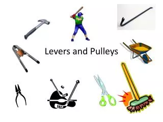
7. IDENTIFY ITEMS THAT APPLY THE PRINCIPLE OF THE WHEEL AND AXLE IN THEIR OPERATION. GIVE AT LEAST TWO EXAMPLES FOR EACH CLASS.
8. Wheel Examples (2nd Class) Doorknob
Screwdriver
Car Climate Controls
Dimmer Switch
Pencil Sharpener
Lamp Switch
Hamster Wheel
Pottery Wheel Car Jack
Telescope/ Microscope Knobs
Windmill/Wind Turbines
Waterwheel
Wheel of Fortune
The Price is Right
9. Wheel Examples (3rd Class) Carousel/Merry-Go-Round
Pizza Cutter
Paint Roller
Fan Blade
Boat or Airplane Propeller
Helicopter Rotor
Big Wheel� Ferris Wheel
Wheelbarrow
Clock Hands
Band Saw
Circular Saw
Blender/Grinder
Bike/Car Tires
Fishing Reel
10. Mechanical Transmission A device which accomplishes one, or more, of the following:
Transfer motion from one point to another
Increase output speed OR force
Change direction of motion
Change type of motion
11. Motion Four types of motion:
LINEAR � Straight line, one direction
RECIPROCATING � straight line, back and forth
ROTATIONAL � Circular
OSCILLATING - Swinging
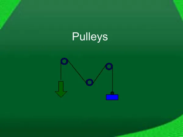
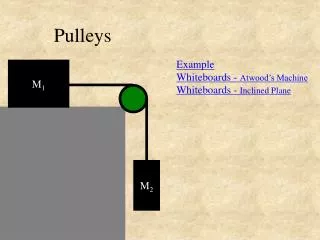
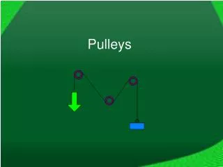
12. Pulleys A pulley is basically a wheel with a groove in the circumference of the wheel, with a belt or cable being fed around the groove.
Pulleys create a mechanical advantage by connecting a small input drive pulley to a larger follower with a belt.
13. MA = FOLLOWER � DRIVER
The Pulley Drive Train above produces an MA of 4. This means 10 lbs of input torque will create 40 lbs output, but the driver must rotate 4 times to rotate output 1 time. Speed is reduced by 4. Mechanical Advantage
14. MA = FOLLOWER � DRIVER Mechanical Advantage
15. Increasing Speed Increase the speed of the output by using a larger driver gear and a smaller follower gear. Speed increases and power decreases.
16. Compound Drive Pulley Trains A Compound Drive Pulley Train has pairs of pulleys working in combination, with the follower of one pulley sharing the same axle as the driver of the next sequential pulley train.
17. Compound Drive Pulley Trains MA = (FOLLOWER 1 X FOLLOWER 2) � (DRIVER 1 x DRIVER 2)
Driver 1 = 2mm Follower 1 = 8mm
Driver 2 = 3mm Follower 2 = 9mm
18. Compound Drive Pulley Trains MA = (FOLLOWER 1 X FOLLOWER 2) � (DRIVER 1 x DRIVER 2)
Driver 1 = 3mm Follower 1 = 9mm
Driver 2 = 2mm Follower 2 = 14mm
19. Problem Sketch the following two pulley trains:
A: Simple pulley train with belt wrapped so both pulleys rotate in same direction.
B. Simple pulley train with belt wrapped so both pulleys rotate in opposite direction.
20. Solution A: Simple pulley train with belt wrapped so both pulleys rotate in same direction.
21. Solution B. Simple pulley train with belt wrapped so both pulleys rotate in opposite direction.
22. Problem Calculate the mechanical advantage of the compound pulley drive train model.
Show your work.
Small Pulley Diameter = 25mm
Large Pulley Diameter = 100mm
23. Pulleys
24. Lifting Pulleys Lifting Pulleys in transmission systems
Single pulley
Moveable pulley
Block and Tackle
25. Single Pulley Provides change of motion, but no mechanical advantage
26. Single Pulley The resistance arm and the effort arm are both the radius of the pulley. Since they are equal, there is no mechanical advantage.
27. Provides change of direction and a mechanical advantage of 1:2 (at the expense of having to increase the amount of line to pull) Moveable pulley
28. Moveable pulley A moveable pulley is a second-class pulley.
The effort arm is the diameter and the resistance arm is the radius.
MA = dE � dR
MA = 2 � 1 = 2
29. Multiple pulleys providing a greater mechanical advantage.
MA is determined by the number of pulleys. Block and Tackle
30. Block and Tackle
31. Block and Tackle
32. Block and Tackle
33. Review Give real-world example of each of the following pulleys.
Force Multiplier
Speed Multiplier
Direction Changer
Give one example of a simple machine or transmission that changes output motion. Identify both input and output motions.