Download
1 / 43
440 likes | 588 Views
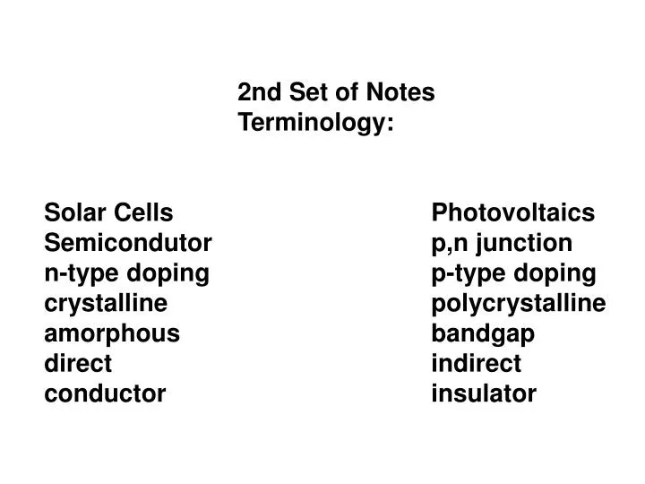
2nd Set of Notes Terminology: Solar Cells Photovoltaics Semicondutor p,n junction n-type doping p-type doping crystalline polycrystalline amorphous bandgap direct indirect conductor insulator. In order to have a fuller appreciation of solar cells:

E N D
2nd Set of Notes Terminology: Solar Cells Photovoltaics Semicondutor p,n junction n-type doping p-type doping crystalline polycrystalline amorphous bandgap direct indirect conductor insulator
In order to have a fuller appreciation of solar cells: • How they function, Use of Materials, Basis of Construction • Need to revisit or visit some basic aspects of materials science. In particular: • materials classification • electronic theories of solids • materials processing • construction techniques and difficulties
Classifications of Materials Solid Liquid Gas Fluid How does the strength of the intermolecular (inter-formula) forces affect whether a molecule is a solid a liquid or a gas?
Focus on Solids Many ways to classify solids Perhaps the broadest categories are: crystalline solids, polycrystalline, and amorphous solids. Crystalline Solids Polycrystalline Solid Amorphous While single crystal materials have long-range order, polycrystalline and amorphous solids only have short-range order.
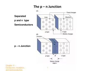
Another broad classification of the solids is based on the conductive properties of the materials. Conductor Semiconductor Insulator Basic Pictures: Conductor Insulator Semiconductor Conductors are typically crystalline materials, semiconductors and insulators can be both crystalline as well as amorphous.
Types of Crytalline Solids Many types of crystalline solids. Consider salt and sugar. Other types of solids have little or no solubility in water. Four Main Types of Crystalline Solids Ionic Solids Molecular Covalent-Network Metallic Each of these different types may form crystalline solids. The regular arrangement of the components of a crystalline solid at the microscopic level produces the beautiful, characteristic shapes of crystals.
The positions of the components in the crystalline solid are usually represent by a lattice a unit cell – primitive cell The unit cell is typically defined by the vectors a, b, and c that point along its sides and the angles alpha, beta, and gamma that describe the angles between these sides. There are only types of unit cells. They differ from one another in terms of the relationships between the lengths of the sides and the angles. Pictures are given
Any of the unit cells, when repeated in space in all three dimensions will form the lattice structure characteristic of a crystalline solid. Simplest case – atomic solid – lattice points are simply the atomic positions For a diatomic crystal MH, the arrangement of M-atoms in space will form a lattice and the arrangement of H atoms will equally form a lattice. This is true if the atoms are uniquely associated such as in covalentmolecule CO or as in an ionic crystal NaCl. CO lattices are offset by the bond length, and for NaCl they are offset by half the unit cell length.
Diamond (fcc) NaCl
How may atoms be arranged in the unit cell? Placement Name Symbol Atoms Placed at the vertices of the parallelepiped Primitive P Additional atom in center of cell body-centered I Additional on opposing faces of the cell c-centered C Atoms on six faces of the unit cell face-centered F
When these four arrangements are considered together with the seven crystal systems considered earlier, not all combinations are possible. Some are forbidden by symmetry and some may be expressible in terms of a smaller unit cell. And the different specifications on a, b, c and alpha, beta, and gamma and P, I, C, and F give
There are 1 triclinic, 2 monoclinic, 4 rhombic, 2 tetragonal, 1 hexagonal, 1 trigonal, and 3 cubic lattices. In fact it is always possible to choose a primitive cell for any lattice; however Centered cells are used so that the full symmetry of the lattice is displayed Thus also, triclinic lattices, with the lowest symmetry are never centered.
The packing of the spheres, the way they are arranged in layers, often determines what type of unit cell results. Consider the cubic unit cells: Simple cubic – three dimensional structure is generated by placing subsequent layers in a way that the spheres in the next layer are directly over the spheres in the lower layer. See: http://www.mhhe.com/physsci/chemistry/essentialchemistry/flash/sphere9.swf
If plane A lies beneath plane B, there are two possible ways of placing an additional atom on top of layer B. If an additional layer was placed directly over plane A, this would give rise to the following series : ...ABABABAB.... This type of crystal structure is known as hexagonal close packing (HCP). If however, all three planes are staggered relative to each other and it is not until the fourth layer is positioned directly over plane A that the sequence is repeated, then the following sequence arises: ...ABCABCABC... This type of crystal structure is known as cubic close packing (CCP) The unit cell of the CCP arrangement is the face-centered cubic (FCC) unit cell. This is not immediately obvious as the closely packed layers are parallel to the {111} planes of the FCC unit cell. There are four different orientations of the close-packed layers.
The coordination number – the number of atoms (or ions) surrounding an atom (or ion) in a crystal lattice. For simple cubic, the coordination number is Body-centered cubic The coordination number here is Face-centered cubic The coordination number of each sphere here is
Simple cubic (P) Body-centered cubic (I) Face-centered cubic (F)
In molecular solids, specific atoms are rarely located at the lattice points as these locations usually have special symmetry requirements. The lattices are simply a symbolic representation of the symmetry of the cells. The lattice is just a matrix onto which the smallest repeating units are hung. These units are often called the
Miller Indices Consider the planes that may be cut through a unit cell. They define the natural “faces” of the crystal Different faces of a crystal often expose chemically different surfaces. For example in palladium the 111 faces have different catalytic activity than the 001 faces. What are these numbers that I have used to define the different faces? Called the
They will be necessary for discussions of X-ray diffraction. • The analysis was popularized by W.H. Miller around 1839. • Essentially the method of characterizing a particular plane that cuts through a crystal is to define the reciprocal of the intersection of the plane with each of the unit cell axes. • For instance if the plane cuts the a axis at ½ a, and the b axis at ½ b, and the c axis at infinity, the reciprocal would be
More generally for a cutting plane that has intersections a/h, b/k, and c/l with the a, b, and c axes respectively: the Miller Indices will be We need consider only cases for which h,k,l are all integers. These are called the – .
Planes that intersect an axis only at infinity have an index of Thus the 010 plane is the plane intersecting the b axis at 1, but containing the a and c axes. Negative intersections are denoted by numbers with a bar above it. _ For instance 2 0 0 denotes a plane that
Often it is easier to visualize the cutting planes in two dimensions. Here are a few examples in two dimensions; And here are a few examples in three dimensions. The notation (h k l) denotes an individual plane, and to specify a set of parallel planes use {h,k,l} So speak of a (1 1 1) plane in a lattice and the set of all {1 1 1} planes that lie parallel to the (1 1 1) plane.
Remember that the smaller the absolute value of h, the more nearly parallel the set of planes is to the a axis they are. {h 0 0} planes are an exception. Same is true for the k and b and the l and c. Crystal faces grow at different rates; the fastest growing faces have the smallest area. So flat molecules tend to form needles Rod like molecules tend to crystallize as plates. These type of arrangements essentially maximize the contact of potentially attractive molecular interactions.
Separation of Planes Miller Indices can be used to express the separation of planes. Consider the separation of the {h k 0} planes in the square lattice: Extension to three dimensions for the planes of a cubic lattice is given by: 1/d2hkl = (h2 + k2 + l2) / a2 And more generally for any orthorhombic lattice: 1/d2hkl = h2 / a2 + k2 / b2 + l2 / c2 These d values are the values are related to the 2 ө values in the X-ray Diffraction data that we’ll see later on.
Suppose that a single monochromaticwave (of any type) is incident on aligned planes of lattice points, with separation d, at angle θ, as shown below. There will be a path difference between the ray that gets reflected along AC' and the ray that gets transmitted, then reflected, along AB and BC respectively. This path difference is The two separate waves will arrive at a point with the same phase, and hence undergo constructive interference, if and only if this path difference is equal to any integer value of the wavelength, i.e. .
Where the same definition of n and λ apply as above. Clearly, and from which it follows that Putting everything together, which simplifies to which is Bragg's law
In modern work use λ = 2d sin өand absorb n into d by regarding the nth order reflection as arising from the{nh,nk,nl} planes
So using sin ө = λ/ 2d; for a cubic unit cell d = a/(h2+k2+l2)1/2 sin ө = (h2+k2+l2)1/2λ / 2athe reflections can then be predicted by substituting the values of h, k , and l into the above eqn.{h,k,l} [1,0,0] [1,1,0] [1,1,1] [2,0,0] [2,1,0] [2,1,1] (h2+k2+l2) 1 2 3 4 5 6 {h,k,l} [2,2,0] [3,0,0] [2,2,1] [3,1,0] [3,1,1] [2,2,2] (h2+k2+l2) 8 9 9 10 11 12 {h,k,l} [3,2,0] [3,2,1] [4,0,0] [3,2,2] [3,3,0] [3,3,1] (h2+k2+l2) 13 14 16 17 18 19 note sin ө = (h2+k2+l2)1/2λ / 2a for (h2+k2+l2) equal 7 and 15 are missing.
The pattern has absences at ө corresponding toh2+k2+l2 = 7 and 15For a cubic system, this is suggestive of the cubic P lattice.