Download
1 / 24
240 likes | 379 Views
Wireless TPS Sensors. Detailed Design Review February 12, 2008. Jesse Pentzer John Sochacki Brandy Holmes Chris Johnson Lucas Wells. Outline. Introduction PCB Sensor Node Software Receiver Node Software X-Jet Packaging VAST Packaging Timeline Budget. Amplifier. CJCs. LDO Regulator.

E N D
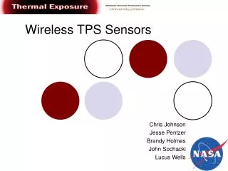
Wireless TPS Sensors Detailed Design ReviewFebruary 12, 2008 Jesse PentzerJohn SochackiBrandy HolmesChris JohnsonLucas Wells
Outline • Introduction • PCB • Sensor Node Software • Receiver Node Software • X-Jet Packaging • VAST Packaging • Timeline • Budget
Amplifier CJCs LDO Regulator LDO Regulator LDO Regulator Pressure Sensor XBee PIC
CJC CJC CJC LDO LDO LDO Amp RTD XBee Pressure
Newest Revision Air-wires will be resolved through testing
Final Concept Final Concept
Final Concept Final Concept
Software Flow Sensor Node • Poll of Sensors • I2C (pressure sensor) • A/D (RTD temp. sensor) • SPI (3 thermocouple temp. sensor) • Communication • USART (XBEE transceiver) • Data Structure Union with Array • Redundant Send
Error Reduction • Program Lockups • Conditional Locked Loops • Watchdog Timer (WDT) • Data Reliability • Redundant Data • Use PIC EEPROM to store old sensor data • Data Comparison
Error Reduction Cont’d • Code Protection • Power Problems • Brown-Out Reset (BOR)
LabVIEW Interface • Communications Parameters • Thermal Coupler graph • Pressure graph • RTD graph • Data Storage in File
LabVIEW Logic Diagram Communication Parameters (user input) Configure Serial Port Set Termination Character Set XON and XOFF Characters Write data to serial port Set I/O Buffer Size Close Session Read Data for buffer Write Data to File Display Data on Graph
X-Jet Preparation Using an aluminum sheet metal box to house electronics. Discs of TPS material allow thermocouples to measure temperature along a centerline through block. Static tube allows pressure measurement inside X-Jet 16
Thermal X-Jet Model • Assumptions: • TPS properties constant • 1-D heat transfer along centerline of TPS Heat Flux Node: Interior Node: Convection Node:
Thermal X-Jet Model – Current Results Heat Flux at q=10000 W/m^2
VAST Flight • Four sensor nodes and the receiver node will be flown. • Pressurized capsule allows the balloon’s internal pressure to be measured. • Capsules made of extruded polystyrene insulation foam. 20
Timeline 22
Beginning Budget $10,943 Shop and UI Fee $1,360 Travel Allocation $7,343 Beginning Spending Budget $2,240 Current Spending Left $957 Budget Status 23
Closing • PCB and Programming are our biggest challenges at this time • We are within budget • Still on track to meet all goals