INDUCTION MOTOR PROTECTION FOR SINGLE PHASING, OVERVOLTAGE AND OVER TEMPERATURE
180 likes | 673 Views
INDUCTION MOTOR PROTECTION FOR SINGLE PHASING, OVERVOLTAGE AND OVER TEMPERATURE. Submitted by:. contents. Project overview Block diagram Power supply Thermistor Comparator Relay Schematic & Working of the project Advantages Applications Future scope Conclusion. Project overview.

INDUCTION MOTOR PROTECTION FOR SINGLE PHASING, OVERVOLTAGE AND OVER TEMPERATURE
E N D
Presentation Transcript
INDUCTION MOTOR PROTECTION FOR SINGLE PHASING, OVERVOLTAGE AND OVER TEMPERATURE Submitted by:
contents • Project overview • Block diagram • Power supply • Thermistor • Comparator • Relay • Schematic & Working of the project • Advantages • Applications • Future scope • Conclusion
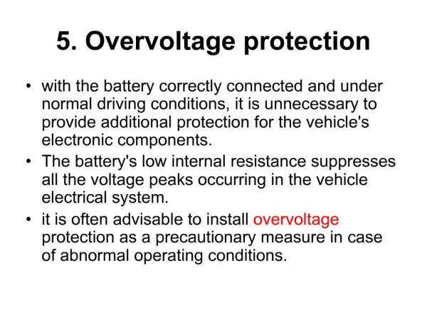
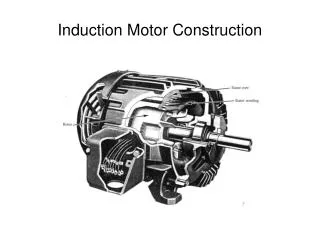
Project overview • The basic idea for the development of the project is to provide safety to the Induction Motor. • If any of the phases, out of the 3 phases is missing and also if the temperature of the motor during operation exceeds the prescribed value, the supply to the induction motor is cut off immediately. • The kit is supplied with a 3phase power i.e., the three transformers are connected to the 3 phases supply.
Contd.. • The 230V AC supply is first stepped down to 12V AC using a step down transformer. • This is then converted to DC using bridge rectifier. • The AC ripples is filtered out by using a capacitor and given to the input pin of voltage regulator 7805. • At output pin of this regulator we get a constant 5V DC which is used for MC and other ICs in this project. • A blocking diode is connected to take the pulsating waveform.
thermistor • A thermistor is a type of resistor whose resistance varies significantly (more than in standard resistors) with temperature. • The word is a portmanteau of thermal and resistor. • Thermistors are widely used as inrush current limiters, temperature sensors, self-resetting over current protectors, and self-regulating heating elements.
comparator • op amps & comparators look very similar • But a comparator gives a logic output indicating the relative potentials on its two inputs • An op amp amplifies the differential voltage between its two inputs – and is designed always to be used in closed-loop applications
Contd.. • Potential dividers are connected to the inverting and non inverting inputs of the op-amp to give some voltage at these terminals. • Supply voltage is given to +V and –V is connected to ground. • The output of this comparator will be logic high (i.e., supply voltage) if the non-inverting terminal input is greater than the inverting terminal input of the comparator. • If the inverting terminal input is greater than the non-inverting terminal input then the output of the comparator will be logic low (i.e., gnd).
relay • A relay is an electrically operated switch. • Current flowing through the coil of the relay creates a magnetic field which attracts a lever and changes the switch contacts. • The coil current can be on or off so relays have two switch positions and have double throw (changeover) switch contacts as shown in the diagram.
Contd.. • Relays allow one circuit to switch a second circuit which can be completely separate from the first. • For example a low voltage battery circuit can use a relay to switch a 230V AC mains circuit. • There is no electrical connection inside the relay between the two circuits, the link is magnetic and mechanical. • To drive relay through MC ULN2003 relay driver IC is used
Working of project • In normal operations RV1, RV2, RV3 & RV4 are so set that the output of the comparators is held low resulting in 4 relays in deactivated condition while the 3CO relay is in active operation. • In the event of failure of any phase the corresponding comparator output goes high that drives the relay the contact of which opens to discontinue the DC supply to the 3CO relay. • The phase motor connected in series with the NO contacts thus open to stop the motor. • Similarly while the temperature goes high on the body of the motor the mounted Thermistor resistance falls to develop logic high for Q4 to operate R4 & disconnect the DC voltage to the 3CO relay. • Thus in the process motor is protected against any phase failure or high temperature.