Programming the Intel 8251 USART for Baud Rates and Serial Communication
This document provides a comprehensive guide on programming the Intel 8251 USART for various baud rates including 2400 and 300. It covers divisor latch settings for different frequencies, communication protocols (asynchronous vs synchronous), and the detailed step-by-step programming instructions. The focus is on setting up communication parameters such as data bits, stop bits, and parity settings, along with valuable insights on the 8251's mode register and command outputs. This serves as a valuable resource for those working with serial data transfer and microcontroller communication.

Programming the Intel 8251 USART for Baud Rates and Serial Communication
E N D
Presentation Transcript
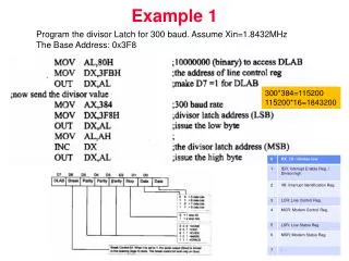
Example 1 Program the divisor Latch for 300 baud. Assume Xin=1.8432MHz The Base Address: 0x3F8 300*384=115200 115200*16=1843200
Example 2 Program the divisor Latch for 2400 baud. Assume Xin=1.8432MHz The Base Address: 0x3F8 2400*48=115200 115200*16=1843200
Example 3 Program 8250 for 2400 baud, 8 data bit, even parity and 1 stop bit. Assume Xin=1.8432MHz The Base Address: 0x3F8 MOV AL,80H ; Accessing DLAB MOV DX,3FBH ;Line Control Register Address OUT DX,AL MOV AX,48 ;baud=2400 115200:48=2400 MOV DX,3F8H ;Low byte of Divisor OUT DX,AL MOV AL,AH INC DX OUT DX,AL MOV AL,00011011 ; DLAB,Break,Even,1 stop, 8 data MOV DX,3FBH ;LCR OUT DX,AL
Synchronous Serial Communication Introduction to USART Intel 8251
Start bit B0 B1 B2 B3 B4 B5 B6 Stop bits Parity Serial Data Transfer • Asynchronous v.s. Synchronous • Asynchronous transfer does not require clock signal. However, it transfers extra bits (start bits and stop bits) during data communication • Synchronous transfer does not transfer extra bits. However, it requires clock signal Frame data Asynchronous Data transfer clk Synchronous Data transfer data B0 B1 B2 B3 B4 B5
(a) Serial data transmitted at the proper rate. (b) The data rate is too fast. (c) The data rate is too slow.
Serial Frame (Synchronous) Bit 7 0 1 2 3 4 5 6 7 0 Time No start or stop bits, timing synchronized with special ASCII characters (SYN)
CRC In SDLC: G(X) = x**16 + x**12 + x**5 + 1
8251 RS232 D[7:0] TxD RD RD RxD WR WR A0 C/D TxC CLK CLK RxC A7 A6 A5 A4 A3 A2 A1 IO/M 8251 USART Interface
7 6 5 4 3 2 1 0 Mode register Number of Stop bits Baud Rate Parity enable 0: disable 1: enable 00: Syn. Mode 01: x1 clock 10: x16 clock 11: x64 clock 00: invalid 01: 1 bit 10: 1.5 bits 11: 2 bits Character length 00: 5 bits 01: 6 bits 10: 7 bits 11: 8 bits Parity 0: odd 1: even Programming 8251 • 8251 mode register
Programming 8251 • 8251 command register EH IR RTS ER SBRK RxE DTR TxE command register TxE: transmit enable DTR: data terminal ready RxE: receiver enable SBPRK: send break character ER: error reset RTS: request to send IR: internal reset EH: enter hunt mode
DSR SYNDET FE OE PE TxEMPTY RxRDY TxRDY Programming 8251 • 8251 status register status register TxRDY: transmit ready RxRDY: receiver ready TxEMPTY: transmitter empty PE: parity error OE: overrun error FE: framing error SYNDET: sync. character detected DSR: data set ready
Read • Write start start Check RxRDY Check TxRDY No No Is it logic 1? Is it logic 1? Yes Yes Read data register* Write data register* end end * This clears RxRDY * This clears TxRDY Simple Serial I/O Procedures
8251 Reset Sequence • write three successive zeros to control address to assure writing a reset to the command register. • write command 40h to reset (reset chip) • After the reset, 8251 expects mode settings • write the mode settings to control address • There after 8251 needs command settings. • write command for command settings.
8251 Coding • Main: • MOV DX,300h • IN AL,DX • MOV AH,AL • MOV DX,309h • Wait • IN AL,DX • AND AL,01 • JZ Wait • MOV AL,AH • MOV DX,308h • OUT DX,AL • JMP Main • MOV DX,309h • MOV AL,0 • OUT DX,AL • OUT DX,AL • OUT DX,AL • MOV AL,40h • OUT DX,AL • MOV AL,4Eh • OUT DX,AL • MOV AL,33h • OUT DX,AL