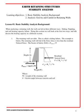
Download
1 / 66
661 likes | 873 Views
Comprehensive guidelines for designing and constructing Mechanically Stabilized Earth (MSE) walls, covering site investigation, wall configuration, stability analysis, and reinforcement specifications. Includes examples, cost estimation, and detailed design considerations.

E N D
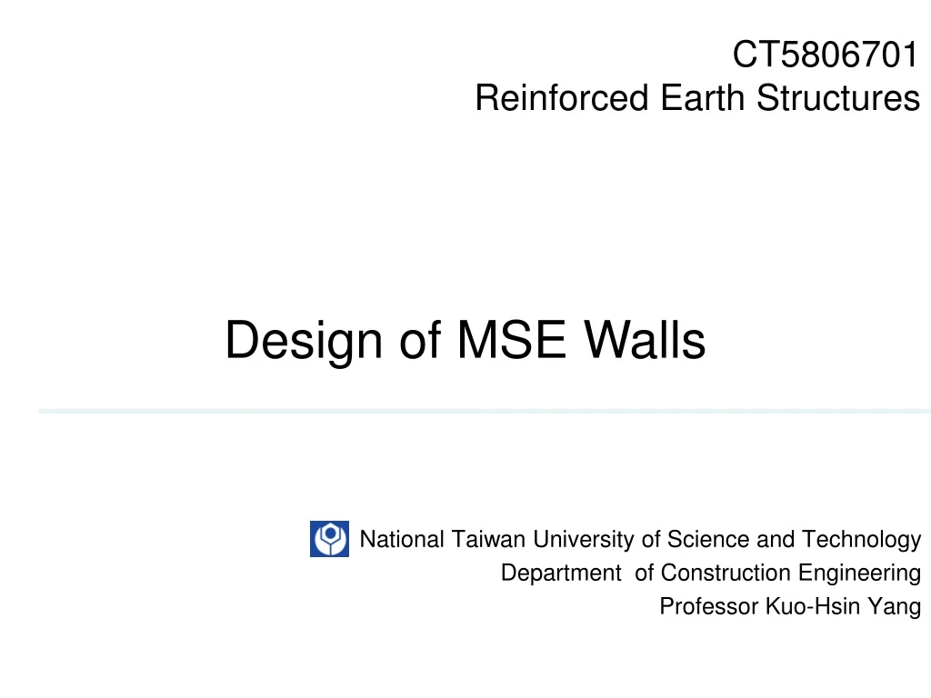
CT5806701Reinforced Earth Structures Design of MSE Walls National Taiwan University of Science and Technology Department of Construction Engineering Professor Kuo-Hsin Yang
Design Guidelines Taiwan • “加勁擋土牆-地工合成加勁材施工綱要第02838 章 V1.0”,公共工程委員會(96年11月) • “加勁擋土結構應用於交通土木工程規範草案之研究(MOTC-STAO-96-04)” ,交通部(97年5月) • “加勁擋土牆設計及施工規範”,內政部營建署(97年6月)
Design Guidelines USA ASSHTO(2002) NCMA (2009) FHWA (2001)
Design Guidelines USA FHWA (2009) includes LRFDinto design
Design Flow Chart Site Investigation Reinforced, Retained Select Critical Cross-Section Foundation Determine Soil and Reinforcement Properties L=0.7H E=H/10 Sv<0.5m Design Wall Configuration and Reinforcement layout NG Stability Analysis Internal, External, Global, Seismic Deformation Settlement OK NG Estimate Cost OK Detailed Design (Drainage, Vegetation) NG Compare with Project Budget OK Complete
Stability Analysis 75%FSstatic FS≥1.3 (Static) FS≥1.1 (Seismic) FS≥1.5 FS≥2.5 FS≥2.0 FS≥1.5 FS≥1.5 walls FS ≥1.3 slope FS≥1.5 walls FS ≥ 1.3 slope Never occurs b/c flexible system Show pictures in Introduction again
Global Stability Limit equilibrium analysis for global stability (cannot calculate by hand) Static Dynamic Rain
Deformation Empirical relationship or FE simulation FHWA (2008), AASHTO (2009) dmax=dRxH/250 (Inextensible) dmax=dRxH/70 (Extensible) dmax H L
Deformation Empirical relationship (Current Research) FE simulation 1. FHWA (2008), AASHTO (2009) Dx H L (L/H)
Tensile Force within MSE Walls Tmax occurs where the reinforcement is intercepted by the failure surface sH Internal Stability against Tmax • Reinforcement breakage • Tmax<Tal Tc t Facing 2. Reinforcement pullout Tmax<Pr=∫tdL Reinforcement 3. Connection Failure Tmax<Talc<Tal Connection Failure First How to evaluate Tmax?
Internal Stability against Reinforcement Breakage
Internal Stability against Breakage Tmax by Earth Pressure Method sH Planar Reinforcement Tmax, i+1 Tmax= sHx Sv (kN/m) Tmax, i Strip Reinforcement Tmax, i-1 Tmax= sHx Sv x SH (kN) Sv Tmax: Maximum Reinforcement Forces (kN/m) sH: Lateral Earth Pressure (Driving Force) (kN/m) Sv: Reinforcement Vertical Spacing(m) Sv: Reinforcement Horizontal Spacing(m)
Internal Stability against Breakage Ko Ka Kr/Ka: Normalized Earth pressure coefficient Ka: Active earth pressure coefficient g: backfill unit weight (kN/m3) z: depth from top(m) q: loading(kN/m2)
Internal Stability against Breakage Active Earth Pressure Coefficient Rankine Ka: For face batter < 8o Coulomb Ka: (face batter, backslope and soil-face interaction) For face batter ≥ 8o
Internal Stability against Breakage Calculate Factor of Safety Tal Change reinforcement type (increase reinforcement strength Tult) FSb= ≥1.5 Tmax Decrease Sv, Increase soil strength FSb: Factor of Safety against Reinforcement Breakage Tal: Allowable Reinforcement Tensile Strength (kN/m) Tmax: MaximumReinforcement Tensile Force(kN/m) Typically, the most critical layer (maximum Tmax) is at bottom Because sh increases with depth
Internal Stability against Reinforcement Pullout
Internal Stability against Pullout Pullout Resistance comes from Soil and Reinforcement Interaction t Tmax Le Pr: Pullout Resistance(kN/m) t: Soil-Reinforcement Interaction Force (kN/m2) (Frictional+Passive Resistance) Le: The length of embedment in the resisting zone(m)
Internal Stability against Pullout Pullout Resistance Pr= CxF*xaxsvxLe Pr: pullout resistance (kN/m) C: the reinforcement effective unit perimeter, C=2 F*: the pullout resistance (or friction-bearing-interaction) factor (use 2/3tand if no pullout tests are performed) a: correction factor to account for reinforcement extensibility. (1.0 for metallic reinforcement, 0.8 for geogrid, 0.6 for geotextile ) s‘v:effective vertical stress on reinforcement (kN/m2) (should exclude live load like traffic load as resistance) Le: reinforcement embedment length (m) (calculate from failure surface)
Internal Stability against Pullout MSE Walls with Extensible Reinforcement H-z Le=L- ≥1m tan(45+f/2) Failure Surface Le:Reinforcement embedment length(m) L: Reinforcement length(m) H:Wall height (m) z:depth from top(m) f:Backfill friction angle(Degree) z L H Le 45+f/2 Rankine
Internal Stability against Pullout MSE Walls with Extensible Reinforcement Considering Face Batter, Backslope and Interface Friction Le Coulomb
Internal Stability against Pullout MSE Walls with Inextensible Reinforcement Le
Internal Stability against Pullout Calculate Factor of Safety Pr Increase reinforcement length Improve pullout factor (different reinforcement with higher F*, a) FSpo= ≥1.5 Tmax FSpo: Factor of Safety against Reinforcement Pullout Pr: Pullout Resistance(kN/m) Tmax:Maximum Reinforcement Tensile Force(kN/m) Typically, the most critical layer (minimum Pr) is at top Because Le increases with depth
Internal Stability against Connection Failure
Internal Stability against Connection Failure Talc FSc= ≥1.5 Increase connection strength (different facing type) Tmax FSc: Factor of Safety against Connection Failure Talc: Allowable Connection Strength (kN/m) (consider creep and durability but not installation damage) Tmax:Maximum Reinforcement Tensile Force(kN/m)
External Stability q Live load, not used for resistant force Vq gr, fr W gb, fb Pq H Pb H/2 H/3 ca, d E gf, ff L Use Coulomb Ka for Sloping back and Inclining Facing ca, d are selected as the minimum values from the reinforcement-foundation or reinforcement-reinforced soil interface shear strength parameters
External Stability against Sliding Increase reinforcement length Improve soil-reinforcement interaction (different reinforcement with higher ca,d) Reduce driving forces Soil nail stabilize the retained zone
External Stability against Overturning Reduce driving forces But never occurs b/c flexible system
External Stability Check Eccentricity Reduce driving forces
External Stability against Bearing Capacity Failure Soil improvement RC or pile foundation also to reduce settlement Reduce eccentricity by reduce driving forces Increase L Effective Area Lower than concrete structure FSbc=3
Internal Stability under Seismic Conditions
Total Reinforcement Load under Seismic Condition Ttotal= Tmax+Tmd Ttotal: Total reinforcement load under seismic condition (kN/m) Tmax: Reinforcement load under static condition (kN/m) Tmd: Additional reinforcement load from seismic loading(kN/m)
Internal Inertial Force under Seismic Conditions PI PI PI=KhWA PI: Internal inertial force from the weight of the backfill in the active zone(kN/m) Kh: Maximum lateral wall acceleration coefficient WA: Weight of the backfill in the active zone(kN/m)
Maximum Lateral Acceleration Coefficient No Wall Facing Displacement Kh=(1.45-A)A Am=(1.45-A) Kh:Maximum Lateral acceleration coefficient (ah/g) A:Maximum ground acceleration coefficient (amax/g) Am:Acceleration amplification factor (ah/amax=Kh/A) ah: Maximum horizontal acceleration inside MSE structures (can larger or less than amax) The value of amax should base on area regulation amax
Site Ground Acceleration Coefficient In Taiwan amax=0.33g or 0.23g
Am vs amax Dynamic Centrifuge Test Shaking Table Test Other factors influence Am such as location, frequency Am vs amax adopted in the design guidelines is on the lower bound of physical data amax<0.4g, Am>1 amax>0.4g, Am<1 Yang, K-H, Hung, W-Y and Kencana, E.Y., (2013) “Acceleration Amplified Responses of Geosynthetic-Reinforced Soil Structures with a Wide Range of Input Ground Acceleration”, ASCE Geo-Congress 2013, San Diego, California, March 2013, Geotechnical Special Publication
Maximum Lateral Acceleration Coefficient Allow Wall Facing Displacement Kh’=(1.45-0.5A)0.5A (1996 AASHTO) Kh’=1.66Kh(Kh/d)0.25 (2001 FHWA) Kh’: Maximumlateral acceleration coefficient when wall facing displacement is allowed A:Maximum ground acceleration coefficient (amax/g) d:lateral wall displacement(25<d<200) (mm)
Additional Reinforcement Load from Seismic Loading Le,i Tmd=PI n SLe,i i=1 Tmd: Additional reinforcement load from seismic loading (kN/m) PI: Internal inertial force from the weight of the backfill in the active zone(kN/m) Le,i: Embedment length of reinforcement (m) n: Number of reinforcement layers
Factor of Safety against Breakage under Seismic Conditions Tult FSdyn, b= RFCRxRFDxRFIDxTmax+RFDxRFIDxTmd ≥75%FSstat Creep reduction factor is not required under seismic conditions
Factor of Safety against Pullout under Seismic Conditions Pr FSdyn, po= ≥75%FSstat Ttotal Where:Pr= Cx0.8F*xaxsvxLe F* reduces 80% under seismic loadings
External Stability under Seismic Conditions
External Stability under Seismic Conditions PIR Inertia Force 50%DPae 50% Dynamic EP increment H/2 Pq Pa Static EP from Surcharge Static EP
External Stability under Seismic Conditions Inertia Force inside MSE Walls PIR=L’HgrKh L’=0.5H
External Stability under Seismic Conditions Dynamic Earth Pressure Pae=Pa+DPae Pesudo-Static (M-O) Approach kv =0
External Stability against Sliding Under Seismic Conditions
External Stability against Overturning Under Seismic Conditions
External Stability Check Eccentricity Under Seismic Conditions