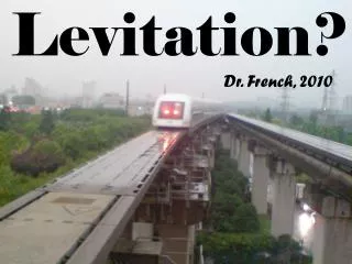
MAGNETIC LEVITATION TRAIN TECHNOLOGY II
170 likes | 413 Views
MAGNETIC LEVITATION TRAIN TECHNOLOGY II. STUDENTS: TONY PEDERSON & TOBY MILLER ADVISOR: DR. WINFRED ANAKWA. TABLE OF CONTENTS. PROJECT SUMMARY PROJECT DESCRIPTION STANDARDS PROJECT DESCRIPTION SCHEDULE OF TASKS. PROJECT SUMMARY.

MAGNETIC LEVITATION TRAIN TECHNOLOGY II
E N D
Presentation Transcript
MAGNETIC LEVITATION TRAIN TECHNOLOGY II STUDENTS: TONY PEDERSON & TOBY MILLER ADVISOR: DR. WINFRED ANAKWA
TABLE OF CONTENTS • PROJECT SUMMARY • PROJECT DESCRIPTION • STANDARDS • PROJECT DESCRIPTION • SCHEDULE OF TASKS
PROJECT SUMMARY The goal of the project is to design a model size train to will be levitated and propelled by electromagnetism. A special magnet array called a Halbach array will be utilized along with a linear synchronous motor to make this train operate.
STANDARDS • ENVIRONMENTAL STANDARDS • Reduction in pollution in the area where they will be used will out way the increased pollution crated by power plants to power the trains. • SAFETY STANDARDS • Must prove that the new technology is safe to use.
PROJECT DESCRIPTION • BLOCK DIAGRAM • TRAIN • TRACK • ELECTRODYNAMIC SUSPENSION • HALBACH ARRAY • LINEAR SYNCHRONOUS MOTOR • CONTROLLER
BLOCK DIAGRAM TRAIN WITH SPEED SENSOR CONTROLLER FREQUENCY REFERENCE SIGNAL FOR SPEED CONTROL THREE-PHASE POWER INPUT TRACK
TRAIN • Made out of aluminum to minimize weight • 4 rows of 8 magnets arranged in a Halbach Array • 2 rows for levitation • 2 rows for lateral guidance and propulsion • May or may not have speed sensor. This will be determined later
TRACK • 2 aluminum guide ways • Wires will be wrapped around guide way to provide the levitation circuits • A G scale model railroad track will be laid between guide ways to provide support for take off and stopping. • A linear synchronous motor will be attached to the track to provide propulsion
ELECTRODYNAMIC SUSPENSION • The magnets on the train produce currents while traveling in the guide way. This uses repulsion to guide and support the train, but will need a support for “landing” and “takeoff” since EDS does not work below 25 mph on a full size train. The minimum speed for levitation will be determined later once the train is built. It has been determined to be a function of magnet size and weight.
HALBACH ARRAY Halbach Array’s are a special arrangement that cancels the magnetic field above the magnets, but still allows a field below the magnets. The permanent magnets that will be using are made out of Neodymium Iron Boron (NdFeB)
LINEAR SYNCHRONOUS MOTOR • Same principle as a rotary synchrounous motor • The rotor will be the Halbach Array • The stator will be coils of wire on the sides of the guide way • The input will be a three-phase varying frequency signal at a very low frequency (2-10 hz)
PRELIMINARY WORK • Almost all time has been spent on research • IEEE Transactions have been very helpful • No track calculations have been made. The train has to be built first to determine weight of train.
EQUATIONS USED OPTIMUM MAGNET THICKNESS =.2*wavelength (lambda) Optimum wavelength = 4*pi*y1 (m) y1 = levitation height (lambda) Br = (Tesla) remanent field of the permanent magnet
PREDICTED TIMELINE SPRING SEMESTER • WEEK 1 - BUILD THE TRAIN. • WEEKS 2-4 - FINISH DESIGNING TRACK AND BUILD IT. • WEEKS 5-12 - TESTING AND DESIGNING A CONTROLLER. • WEEKS 13-16 – PREPARING FOR FINALE PRESENTATION.