Download
1 / 23
230 likes | 258 Views
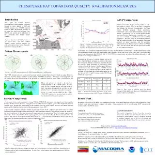
This study evaluates different antenna pattern measurement methods to determine any significant differences in velocity measurements. It includes site overview, calibration methods, AIS pattern software, data reprocessing, and results analysis. The research aims to correct magnetic field distortions, bearing errors, and velocity errors for improved accuracy. Findings show little variation between methods at certain bearings, with plans to enhance baseline currents with a new site.

E N D
Evaluation of Three Antenna Pattern Measurements for a 25 MHz SeaSonde Colin Evans, Hugh Roarty, Ethan Handel, Scott Glenn Rutgers University, USA
Quick Outline • Motivation for examination • Site overview • Description of antenna pattern calibration methods and processing • New AIS-pattern generation software • Data Reprocessing • Results • Summary
Motivation Determine any significant differences in velocity measurements at the radial and total level between antenna pattern measurement methods. Determine advantages and disadvantages between APM methods
25 MHz SILD System Setup computer essentials AIS antenna shed with climate-controlled enclosure transmitter receiver combine tx/rx antenna (inside the enclosure) Data backup UPS system AIS receiver
Examination Area and Overview of 25 MHz Network Baseline from SILD to PORT is 176 degrees. Bearing values are in SILD range cell 9 (8.998km offshore). Bearing values 102,132,and 167 are inPORTrange cells 12, 8, and 4, respectfully.
Why Do We Measure Patterns? • Corrects for distortions in the magnetic field • Corrects for bearing errors • … which, in turn, corrects for velocity errors • More accurate than assuming ideal pattern • More can be read about antenna pattern measurements on CODAR support page: http:support.codar.comTechnicians_Information_Page_for_SeaSondes/Training_Files/Day2_PatternMeasurements_2014.pdf
Pattern Methods Walking Boat AIS - 25 MHz system = ~12 m wavelength - Rule of thumb suggested by CODAR is to be more than 1 wavelength away from the antenna (and other objects) during pattern calibration ~35 m
AIS Pattern Generation Software – More Detailed • Two important launch agents: • AIS Logger • AIS Webserver • Trak files created every 10 minutes • Loop files created daily http://sprk-maracoos.dyndns.org:8241
Processing the Patterns AIS filtering Walking and Boat filtering
Pattern Results Walking – 10o smooth Boat – 10o smooth AIS – 12o smooth
Pattern Amplitudes Walking red dashed = ideal L1 blue dashed = ideal L2 red solid = measured L1 blue solid = measured L2 Boat AIS
Data Reprocessing • Spectra files reprocessed with batch reprocessing application built by CODAR Outputs Inputs Radials CSS files Analyze Spectra Radial Shorts Radial Configs Wave data Walking APM Boat APM AIS APM
Walking Boat AIS software
Hourly Velocity Comparisons Black – Ideal Blue – Walking Red – Boat Light Blue - AIS
Correlation between SILD Measured and Ideal Radials R Values
Walking Total Comparisons Boat AIS 2014-10-16 12:00:00
Total Comparisons Walking Boat AIS 2014-10-16 13:00:00
Total Comparisons Walking Boat AIS 2014-10-16 14:00:00
Total Comparisons Walking Boat AIS 2014-10-16 15:00:00
Total Comparisons Walking Boat AIS 2014-10-16 16:00:00
Total Comparisons Walking Boat AIS 2014-10-16 17:00:00
Summary/Review • We found little variation between calibration methods at bearings 102 and 132 on the radial and total level • Decline in correlation at bearing 167 • We can rely on several APM methods is one is not possible • Currently in the process of installing a 3rd 25 MHz NYH site to improve baseline currents