Download
1 / 16
170 likes | 371 Views
Case, Power Supply, and Motherboard Types. AT Style: Original style of cases and motherboards, based on the 1 st IBM PC-XT design. The power supply has 2 six-pin header connectors labeled P8 and P9, which provide +/-5VDC, +/-12VDC, signal, and ground.

E N D
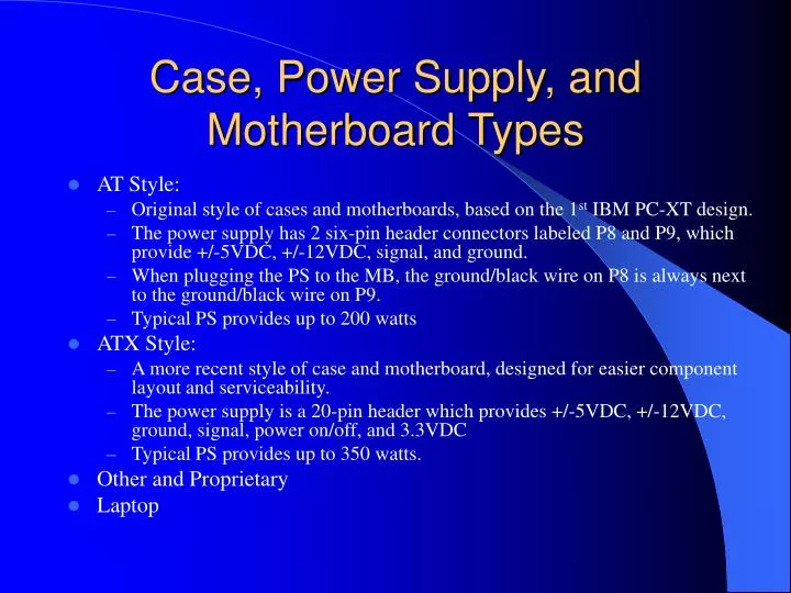
Case, Power Supply, and Motherboard Types • AT Style: • Original style of cases and motherboards, based on the 1st IBM PC-XT design. • The power supply has 2 six-pin header connectors labeled P8 and P9, which provide +/-5VDC, +/-12VDC, signal, and ground. • When plugging the PS to the MB, the ground/black wire on P8 is always next to the ground/black wire on P9. • Typical PS provides up to 200 watts • ATX Style: • A more recent style of case and motherboard, designed for easier component layout and serviceability. • The power supply is a 20-pin header which provides +/-5VDC, +/-12VDC, ground, signal, power on/off, and 3.3VDC • Typical PS provides up to 350 watts. • Other and Proprietary • Laptop
PC-Bus 8-bit Extended ISA (EISA) 32-bit MCA (IBM proprietary) 32-bit VESA Local Bus 32-bit Standard ISA 16-bit PCI 32-bit APG (graphics adapter only) 32 through 128 bit PCMCIA Type 2/3 (laptop) 16/32 bit Expansion Slot Architecture
Case Designs • Desktop • Sit horizontally on a desk • Towers • Vertically on the floor besides the desk • More bays for I/O devices, depending on heighth of tower • Can have cooling problems due to card placement • Rackmount • Typically heavy duty construction • Designed to be installed in a colo or telco rack • Laptop/portables
Socket 7 Pentium & AMD K5 Super 7 Pentium MMX Socket 8 Pentium Pro Socket 370 Celeron FC-PGA 370 Celeron & Pentium III Socket A AMD Athlon & Duron Socket 423/468 Pentium 4 Note: These charts are simplified for the sake of clarity CPU Sockets
CPU Cartridge Form Factors • SEPP • Single Edge Processor Package • The PCB is open on both sides • Celeron using slot-1 converters • SECC • Single Edge Contact Cartridge • Both sides have a plastic cover • Pentium II and early Pentium III • SECC-2 • Only the back has a cover • Xeon and later Celeron & Pentium III
CPU Slots • Slot 1 • Celeron, Pentium II, and early Pentium III • Slot 2 • Xeon • Slot A • AMD Athlon
System Resources:IRQs and I/O Addresses Important Resources: • IRQ2 Cascade to IRQs 8-15 • IRQ3 COM2 3F8h / COM4 3E8h • IRQ4 COM1 2F8h / COM3 2E8h • IRQ5 NIC/ LPT2 278h • IRQ6 FDD 3F0h • IRQ7 LPT1 378h • IRQ14 IDE1 1F0h • IRQ15 IDE2 170h Complete list is on pp 151-157
Video Standards Standard Type Max Resolution Text Display Refresh rates Connector Type MDA T 720x348 80x25 50-60Hz RCA CGA T/G 640x200 80x25 60 DB9 EGA T/G 720x348 80x25 60 DB9 VGA T/G 720x400 80x43 60-70 DB15 SVGA T/G 1600x1200 80x43 50-72 DB15
Modern I/O Port Types • Keyboard • 5-pin DIN or PS/2 6-pin mini-DIN • Mouse • DB9M or PS/2 6-pin mini-DIN • Serial • DB9M or DB25M • Parallel • DB25F • Video • DB15F-3 • Game • DB15F-2 • Modem • RJ11F • Network • RJ45F or BNC • Sound • RCA-F or 1/8” tip/ring-F • SCSI • 50-pin Centronics, DB25F, mini-DB25F, others • USB • USB/A-F • Firewire • Firewire/A-F
Standard I/O Ports • RS-232 Serial • 1 data line, up to 115Kbps • Can handle synchronous or asynchronous transmission • Is controlled by either a 8-bit or 16-bit UART • Connection between like serial devices is done via a null-modem cable • Centronics Parallel • 8 data lines, up to 115Kbps • 10 foot practical length • USB • Can handle up to 127 devices on the bus using just 1 IR, buffer address range, and DMA • Up to 10Mbps • IEEE 1394/Firewire • Can handle up to 64 devices on the bus just 1 IR, buffer address range, and DMA • Up to 400Mbps
Hard Drive Interface Types • MFM/RRL/Winchester • Easily recognizable by the fact that there are 2 data cables that connect the controller to the drive • Oldest of the drive types • 1 drive per interface card • IDE • Generally, a lower cost drive solution • 40-pin cable • 2 drives per interface card, 2 cards total • A drive can be set as a slave or a master on its card, or the drive can depend on “cable select” for its assignment • SCSI • 50-pin cable for SCSI-1 and -2, 68-pin for SCSI-3 • 8 addresses per interface card daisy chain (of which the card uses address #7 and the boot drive uses #0). Each address can have 4 Logical Unit Numbers (LUNs) • Termination is required at the ends of each SCSI bus • Maximum length of a daisy chain is 20 feet, with each segment being a max of 3 feet. Refer to page 188 for complete list of specifications