Download
1 / 57
740 likes | 1.81k Views
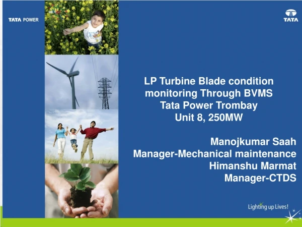
LP Turbine Blade condition monitoring Through BVMS Tata Power Trombay Unit 8, 250MW Manojkumar Saah Manager-Mechanical maintenance Himanshu Marmat Manager-CTDS. Turbine Maintenance. Contents. Turbine Introduction and History of machine Trigger point for BVMS installation

E N D
LP Turbine Blade condition monitoring Through BVMS Tata Power Trombay Unit 8, 250MW Manojkumar Saah Manager-Mechanical maintenance HimanshuMarmat Manager-CTDS Turbine Maintenance
Contents • Turbine Introduction and History of machine • Trigger point for BVMS installation • Introduction of BVMS and its advantages • BVMS installation and commissioning • Analysis of effect of running parameters on blade vibration • OEM Support
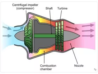
250 MW Turbine Introduction • Turbine was put on turning gear on 24.12.2008 and unit first synchronized on oil on 24.01.2009 and COD Completed on 29.03.2009. • Unit 8 Steam turbine is a tandem compound machine with separate HP, IP and LP sections. • The HP and IP sections being single flow cylinders and LP sections double flow cylinder. • The HP Turbine has barrel type outer casing (25 stages). • The IP Turbine has single flow construction with horizontally split casing (17 stages). • The LP Turbine has double flow split casing (8 stages). .
First time crack Detection on LPT Blades • First outage was carried out in July 2011 for inspection of 250 MW Generator and Turbine Bearing along with visual inspection of LP Turbine last stage free standing blades (3L &3R). • During LP Turbine Roll check, roll check values were found very less and inconsistent so it was decided to remove LP Inner-inner casing for rotor inspection and flow path measurement. • Radial clearances were found very less and inconsistent. And LP rotor lifted off for correcting Flow path clearances by grinding of casing fins.
First time crack Detection on LPT Blades (Trombay Unit 8,250MW is having advance class of LP turbine Blades. These advance class of LP turbine blades are installed by BHEL in around 25 sites in India. At few of those sites, cracks had been observed at blade root of LP Stage blades during inspection) • During the correction of LP turbine flow path, a technical discussion took place with M/s BHEL and it was decided to carry out MPI of LP Turbine last stage free standing blades (3L &3R). • Cracks were detected at root of two blades of generator side (Blade tag No: 32040 sl no.37 and 32042 sl.no.39) and one blade of turbine side at transition zone of root and blade profile(Blade tag No.32039 sl no.37). Same had been replaced.
Data Collection and analysis / Fact finding • A detail investigation was initiated to find out the root cause of cracks in LP turbine free standing blades at Trombay Unit 8,250MW. Following actions were taken • A visit was made to “Suratgargh Thermal Power Station” where catastrophic failure of LP turbine in 250MW Unit 6 had taken place thrice since commissioning in Dec-2009. • In situ MPI of free standing blades carried out during a short shut down in March 2012. No defective bladed detected. • LP turbine spray hood system checked for any passing of water and direction of water jet. Everything was found in order. • Orientation of LP Bypass spray system was checked, no deviation observed. • LP Heater 2 & 3 drain line modified in such a way to avoid the high level of LP Heaters.
Blade Vibrations Monitoring System • We had requested M/s BHEL to investigate the root cause of the blade failure. In addition to the action taken as mentioned above, M/s BHEL proposed to install Blade Vibration Monitoring System (BVMS) to monitor the health of LP turbine free standing blades. • The BVMS & STVMS system was installed in Trombay U8 LP Turbine of during Dec 2012 outage. Unfortunately, it could not be commissioned in Dec-2012 outage due to non availability of Monitoring System.
Jan 2014 Catastrophic Failure • On 9th January 2014, at 22:56.06 hrs, unit 8 was generating 182 MW and suddenly loud noise was heard from turbine deck along with Diff. Expansion LPT Hi alarm on CRT. • At 22.56.07.868 hrs, Turbine tripped on over speed protection (class B operated). Machine speed maximum 3020 RPM. MT HP abs shaft vibration front (X-dir) shot up to 716 microns. All bearing pedestal vibrations went off scale (200 microns). Generator tripped on reverse power, Class A operated. Both GT breakers opened and fast changeover took place. Fire seen out in between LP turbine and generator. • Unit tripped due to actuation of over speed bolt. Simultaneously bearing high vibrations & rise in bearing metal temperature observed. LP Turbine blade (generator end) failure caused rotor imbalance and very high vibrations resulting in lube oil leak and escape of hydrogen gas from generator shell. High unbalance forces due to breaking of LP rotor blade have caused damage to bearing pedestals and disturbance in generator seals, resulting in lube oil leak and escape of hydrogen gas from generator shellwhich resulted in huge fire.
Photos of Damage: HPBP & Extraction NRV Rack HP Bypass system Rack of Extraction NRVs
Photos of Damage: Bearing Pedestals Damaged Turbine Bearing Keys and packers LP-Generator Bearing pedestal (damaged LP Gland box, broken pedestal parting plane bolts)
Photos of Damage: LPT Blades LP3L Sheared off blade from root
Photos of Damage: LP Turbine outer casing Broken piece of blade pierced the LPT outer casing
Re-installation and Commissioning of BVMS Benefits of BVMS • The system can trend and detect high vibrations of individual blades arising out of deterioration of the blades, missing blades, undue resonance, rubbing, cracks, etc. • Generation of Experimental Campbell diagram that can be validated with design data to ensure the integrity of all the blades of LP3L and LP3R during coast up and coast down. • Online monitoring and trending of blade deflection and blade vibration of all the 48 blades in LP3L and LP3R • Correlate the operating parameters like load, condenser vacuum with blade vibration and thus avoid rough zones of operation w.r.t. blades
Benefits of BVMS • Benefits Better understanding of vibration behaviour of LP turbine free standing blades during running of turbine – Leading to condition monitoring of blades • Effect of installation on operation of machine Non interference with the operation, design and overhaul of the turbine – practically, no change in the machine as Monitoring is based on non contact sensors.
Introduction to BVMS • BVMS shows following vibration of LPT free standing blades (3L &3R) in micron (Pick-pick) • Average Blade vibration – Turbine End ( Alarm at 400 micron) • Max. Blade vibration – Turbine End ( Alarm at 900 micron) • Average Blade vibration – Generator End ( Alarm at 400 micron) • Max. Blade vibration – Generator End ( Alarm at 900 micron)
Introduction to BVMS • Sensors On Turbine Side FIVE sensors and on Generator side FIVE Sensors have been installed Three at Mid Chord -- For redundancy One at Leading Edge -- Blade Twist One at Trailing Edge -- Blade Twist
Introduction to BVMS LPT Pre Amplifiers Key Phasor input BVMS Real Time • Real Time Display: • RPM • Sensor Status • Average and maximum lean of TE and GE LP Blades • Long Term Displays (Available to OEM): • Historical Trend of Blade Lean • Historical Trend of Blade Twist • Track in resonance shifts • Stores and mirrors all data • Web Server host • Provide notification Long Term
BVMS Installation Location of Sensor installation on Lower Half of Diffuser Casing Twelve Ø125mm holes offer possible sensor locations