Structural Steel Beams: Types, Design, and Strength Calculation
Learn about different types of steel beams and how to calculate their elastic and plastic section moduli, yield and plastic moments, lateral stability, flange load buckling, and more.

Structural Steel Beams: Types, Design, and Strength Calculation
E N D
Presentation Transcript
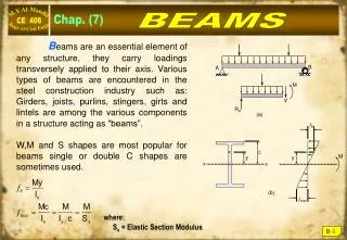
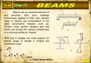
B A M fb V RA (a) c M y y x x (b) fmax BEAMS Chap. (7) Beams are an essential element of any structure, they carry loadings transversely applied to their axis. Various types of beams are encountered in the steel construction industry such as: Girders, joists, purlins, stingers, girts and lintels are among the various components in a structure acting as “beams”. W,M and S shapes are most popular for beams single or double C shapes are sometimes used. where: Sx = Elastic Section Modulus B-1
f < Fy moment f = Fy (a) Fy (b) Fy (c) (d) Fy C = AcFy a Plastic neutral axis T = AtFy Fy ( M My ) Elastic Bending • M < My • My = FySx • Sx = Elastic section Modulus • My< M < Mp • Mp = Fy Z • where: • Z = = Plastic Section Modulus. • a = distance between centroids of two half • areas (Use T – section properties) B-2
Calculation of My & Mp Example B - 1 For the built-up shape shown below, Determine A) Elastic Section Modulus (Sx). B) Yield Moment (My). C) Plastic section Modulus (Z). D) Plastic Moment (Mp). Use A 572 – Gr 50 steel? Solution: B-3
My & Mp for rolled sections Example B - 2 Calculate My & Mp for W 10x60 of A-36 steel. Solution: My = Fy Sx = 36 x 66.7 = 2401.2 in-kip. B-4
As the case with columns, the compression flange could buckle, but the restraining tension flange will cause the compression flange to buckle in “Lateral – Torsional Buckling” (LTB) mode. This can be reduced or eliminated by laterally supporting the compression flange. Lateral Stability LFRD approach for bending: Mu ≤ b Mn where, Mu = controlling combination of factored load moments. b = resistance factor for beams = 0.90 Mn = normal moment strength of the beam If the beam is allowed to reach the fully plastic stage, then; Mn = Mp B-5
Lateral Stability - Contd. It is also possible that elements of the compression flange will buckle prior to over-all yielding of section, this is called “Flange Load Buckling” (FLB), or the compression part of the web could buckle locally under “Web Local Buckling” (WLB). The controlling factor for FLB & WLB are the width-thickness ratios of the compression elements. Remember that the flanges of (I, W & S) shapes are unstiffened elements, while the webs are stiffened elements. B-6
Classification of Shapes AISC classifies shapes subjected to full compression or to partial compression due to bending as: compact (C) non-compact (NC) or slender (S); depending on their Width to thickness ratio. Upper limit for compact shapes. Upper limit for non-compact shapes. This table is summary of Table B 4.1 (page 16.1-16) Width-Thickness Parameters* the shape is “compact” (C). the shape is “non-compact” (NC). the shape is “slender” (S). p r Element Flange Web *For hot-rolled I and H-shapes in flexure. B-7
LRFD Beam Selection Chart Local Buckling Criteria (B-4) (p r) BEAMS in Flexure (chapter F) (W, M & S) shapes only Columns in compression (chapter E) Compact or Non-compact (AISC E-3) Slender (Q-Factor) (AISC E-7) Compact Flanges Compact Webs (AISC F-2) Non-compact Flanges (compact webs) (AISC F-3-1) Slender Flanges (compact webs) (AISC F-3-2) Slender webs (AISC F-5) -Not included- Non-compact webs (AISC F-4) -Not included- B-8
Bending Strength of Compact Shape A compact shape (W,M, S or C) is defined as with webs constantly attached to flanges, and satisfies: Most rolled shapes satisfy the compact criteria, and if the unbraced length (Lb) is very short (or zero) then : Mn = Mp = Fyz (AISC F2.1) B-9
30' Capacity of Compact Beams Example B - 3 Check the adequacy of W 16 x 31 made of A-36 steel to support a reinforced concrete slab with a service dead load of 450 lb/ft in addition to a service live load of 550 lb/ft. wD = 450 lb/ft wL = 550 lb/ft Solution: wD = 450 + 31 = 481 ib/ft (including self wt.) wu = 1.2 wD + 1.6 wL = 1.2 x 0.481 + 1.6 x 0.550 = 1.457 k/ft Mu = ⅛ wuL2 = ⅛ x 1.457 x (30)2 = 164 k·ft. Check Compactness: Mn = MP = Fyz = 36 x 54 = 1944 k·in = 162k·ft b Mn = 0.9 x 162 = 146 ft·k < 164 ft·k (N.G.) O.K. B-10
w 20' Design of Compact Beams Example B - 4 Select the lightest (W) or (M) shape to resist a uniformly distributed dead load of (0.2) kip/ft and live load of (0.8) kip/ft. The beam is simply supported and the compression flange is fully braced (Lb = 0). Use a) A-36steel b) A572 – Gr 50 steel Solution: Wu = 1.2WD + 1.6WL = 1.2 x 0.2 + 1.6 x 0.8 = 1.52 k/ft (not including beam wt.) a) A-36 steel :- bMn = bMP = bFyZx ≥ Mu Best Choice W 12 × 22 Zx = 29.3 in3 W 10 × 26 Zx = 31.3 in3 W 8 × 31 Zx = 30.4 in3 Select W12 x 22 (A-36 Steel) B-11
Design of Compact Shapes Check Compactness: Check strength including self weight: Mn = 0.9 × 29.3 × 36/12 = 79.1 k·ft > Mu (O.K.) b) A-572- Gr 50 steel Required Select W10 x 19 (Zx = 21.6 in3). (LFRD Table 3-2) Check Compactness: Check strength: bFyZx = 0.9 × 21.6 × 50/12 = 81 k·ft (O.K.) B-12
(Lb) Lateral Bracing Length The moment strength of compact shape is a function of the unbraced length (Lb), defined as the distance between points of lateral support (denoted by x). • If Lb ≤ Lp Full Plastic Moment (Mp) • If Lp < Lb ≤ Lr In elastic Lateral Torsional Buckling • If Lr < Lb Elastic Lateral Torsional Buckling where: (AISC F-2.5) (AISC F-2.6) B-13
LRFD Design of Compact Beams 1 – Full section Yielding (Lb ≤ Lp): Mn = Mp = FyZx (AISC F 2.1) 2 – Inelastic Lateral Torsional Buckling ( Lp < Lb ≤ Lr ): 3 – Elastic Lateral Torsional Buckling (Lr < Lb): Mn = Fcr Sx ≤ Mp (AISC F-2.3) where: J = Torsional constant (in4). ho = Distance between flanges centroids (in). C = 1.0 for w shapes. rts = radius of gyration of the compression flange plus one-sixth of the web. B-14
(Cb) Moment Gradient Factor Equations (F 2.2) & (F2.4) for compact beams affected by lateral torsional buckling, require the introduction of the “Moment Gradient Factor” (Cb) for non-uniform bending moment values between the lateral bracing points for (Lb). AISC provides value for Cb as: The effect of Cb on Nominal Strength is shown below: B-15
(Cb) Examples on Moment Gradient Factor Example B - 5 Determine (Cb) for a uniformly loaded, simply supported beam with lateral supports at its ends only. Solution B-16
(Cb) Some Examples on For unbraced cantilever beams, AISC recommends the value of Cb = 1.0. A value of Cb = 1.0 is always conservative and represent uniform banding throughout the unbraced length (Lb), (See Table 3-1) AISC. B-17
Example on Bending of Compact Sections Example B - 6 • Determine the design strength (b Mn) for W14 68 made of A-572-Gr50 steel and: • Continuous lateral support. • Unbraced length = 20 ft, Cb = 1.0 • Unbraced length = 20 ft, Cb = 1.75 Solution A) Check compactness: web is always compact ! Mn = Mp = FyZ = 20 115 = 5750 in·k = 479 ft·k. b Mn = 0.9 479 = 431 ft·k. B) B-18
Continued: Since Lp < (Lb = 20 ft) < Lr Equation F – 2.2 controls: b Mn = 0.9 316.25 = 284.6 ft·kip. • For Cb = 1.75, other conditions unchanged: • Mn = 1.75 316.25 = 553.4 ft·k. • Since Mn ≤ Mp, • then Mn = Mp = 479 ft·k • bMn = 0.9 479 =431 ft·k. B-19