Download
1 / 37
370 likes | 484 Views
Explore UML behavioral diagrams such as sequence, collaboration, state-transition, and activity diagrams. Discover the key views of UML, including use-case view, logical view, component view, concurrency view, and deployment view. Learn about static and dynamic structures in various UML diagrams and how they depict interactions between objects and systems. Dive into sequence and collaboration diagrams to understand message passing and system functionality. This lecture outline covers the syntax and instances in collaboration diagrams, enabling a deeper understanding of object-oriented analysis and design.

E N D
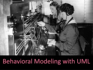
Behavioral Modeling with UMLBehavioral DiagramsInteraction DiagramsSeree Chinodom Object Oriented Analysis and Design
Lecture Outline • UML Behavioral Diagrams • Interaction Diagrams • Sequence Diagram • Collaboration Diagram
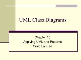
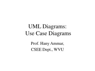
UML has 9 kinds of diagrams • Class Diagram • Object Diagram • Component Diagram • Deployment Diagram • Use Case Diagram • Sequence Diagram • Collaboration Diagram • StateTransition Diagram • Activity Diagram Structural Diagrams Functional Diagrams Behavioral Diagrams
UML(Unified Modeling Language) • 5 มุมมองหลักของ UML • Use-case view : หน้าที่การทำงานของระบบซอฟต์แวร์ โดยพิจารณาจากมุมมองของผู้ใช้ภายนอก หรือ ระบบภายนอก • use-case diagram • Logical view : หน้าที่การทำงานของระบบมีโครงสร้างอย่างไร มองในรูปของ static structure และ dynamic behavior • class diagram, object diagram, state, sequence, collaboration, activity diagrams
UML(Unified Modeling Language) • Component view : องค์ประกอบย่อยในการ implement ที่ประกอบเป็นระบบ และ dependency ระหว่างองค์ประกอบเหล่านั้น • component diagram • Concurrency view: การแบ่งแยก process และ processors โดยพิจารณาทั้ง communication และ synchronization • dynamic diagrams (state, sequence, collaboration activity) • implementation diagrams(component และ deployment) • Deployment view : โครงสร้างทางกายภาพเกี่ยวกับ การติดตั้ง และใช้งานระบบ • deployment diagram
Static & Dynamic views • ระบบใดๆ มักประกอบด้วยโครงสร้าง 2 แบบ ได้แก่ • static และ dynamic • โครงสร้างของ Use Case และ Class Diagram เป็นแบบ static • แสดงองค์ประกอบของระบบ คลาส แอททริบิวต์ เมทธอด และ ความสัมพันธ์ระหว่างคลาส • ไม่ระบุขั้นตอนการดำเนินงาน ลำดับการทำงานก่อนหลัง • โครงสร้างของ Behavioral Diagrams เป็นแบบ dynamic
Behavioral Diagrams • Behavioral Diagrams เป็นโครงสร้างแบบ dynamic • 4 diagrams ได้แก่ • Sequence Diagram • Collaboration Diagram • State-transition Diagram • Activity Diagram Interaction Diagrams
Interaction diagrams • แสดงการปฏิสัมพันธ์ระหว่างกลุ่มของวัตถุ • มักใช้อธิบายสถานการณ์ของ use case 1 use case • อธิบายการติดต่อสื่อสารระหว่างวัตถุ • 2 รูปแบบ • Time-based (Sequence Diagram) • Organization-based (Collaboration Diagram)
Sequence & Collaboration Diagrams • ทั้ง 2 diagrams แสดง message ที่ถูกส่งผ่านระหว่างวัตถุที่ทำงานร่วมกัน เพื่อประกอบเป็นหน้าที่การทำงานของระบบ • Sequence diagrams เน้นmessage ที่เกิดขึ้นตามลำดับของเวลา • Collaboration diagrams เน้นการเชื่อมต่อทางด้านโครงสร้างระหว่างวัตถุที่ทำงานร่วมกัน
Sequence & Collaboration Diagrams • ทั้ง 2 diagrams สามารถใช้ในการจำลองการปฏิสัมพันธ์ระหว่างวัตถุ กับระบบทั้งหมด • หรือ อาจใช้ในการจำลองปฏิสัมพันธ์ที่เกี่ยวข้องใน Use Case ใด Use Case หนึ่งโดยเฉพาะ
registration registration math 101 math 101 : Student form manager section 1 1: fill in info 2: submit 3: add course(joe, math 01) 4: are you open? 5: are you open? 6: add (joe) 7: add (joe) A Sequence Diagram
1: set course info course form : 2: process CourseForm 3: add course : Registrar theManager : aCourse : CurriculumManager Course 4: new course A Collaboration Diagram
Construct Description Syntax Instance (object, data value, component instance etc.) An entity with a unique identity and to which a set of operations can be applied (signals be sent) and which has a state that stores the effects of the operations (the signals). name attr values A specification of an executable statement. A few different kinds of actions are predefined, e.g. CreateAction, CallAction, DestroyAction, and UninterpretedAction. textual Action Interactions : Core Elements
Construct Description Syntax Stimulus A communication between two instances. textual A declaration of a service that can be requested from an instance to effect behavior. Operation A specification of an asynchronous stimulus communicated between instances. «Signal»Name Signal parameters Interaction : Core Elements (cont’d)
Construct Description Syntax Link A connection between instances. A named slot in an instance, which holds the value of an attribute. textual Attribute Link Return A return from method call Interaction: Core Relationships
Sequence diagrams • แสดงการปฏิสัมพันธ์ระหว่างวัตถุตามลำดับเวลา (time sequence) • ประกอบด้วย • actor หรือ object ที่มีปฏิสัมพันธ์กับวัตถุอื่นๆ • เส้นชีวิต (lifeline) • Message ที่ส่งผ่านระหว่าง Object หรือ actor
Content of sequence diagrams • Actor หรือ วัตถุ (Objects) • แลกเปลี่ยน messages ให้แก่กันและกัน • เส้นชีวิต (Lifeline) • แสดงว่าวัตถุถูกสร้างขึ้น และยังไม่ถูกทำลาย • Messages • Synchronous : “call events,”แทนด้วย full arrow • Asynchronous: “signals,” แทนด้วย half arrow • «create» และ «destroy» messages
Messages • message ที่ส่งผ่านระหว่าง objects สนับสนุนการปฏิสัมพันธ์ระหว่างวัตถุ • เป็นวิธีการที่ object ใช้ในการขอรับบริการจากวัตถุอื่นๆ • object ใดๆ ติดต่อสื่อสารกับ object อื่นๆ ผ่านทาง operation ของวัตถุนั้นๆ
Message Types • Simple • Sender / Receiver • ไม่ระบุรายละเอียดของวิธีการติดต่อสื่อสารระหว่างวัตถุ • Synchronous • เรียกใช้ Operation ของวัตถุ โดย Sender/Caller รอจน สิ้นสุดOperation • Receiver จัดเป็น passive object • Asynchronous • ไม่มีการ return กลับไปยัง Sender/Caller • Sender ทำงานต่อทันที่ที่ส่ง message • Receiver จัดเป็น active object
Message Notation Simple Synchronous Asynchronous (Message return)
object symbol name : Class other lifeline stimulus name (…) activation new (…) : Class message delete create return Notation : Sequence Diagram
Flat Flow Asynchronous Flow Nested Flow appl err handl alarm caller exchange callee : Article teller : Order lift receiver unknown alarm getValue dial tone dial digit price dial digit ringing tone getName ringing signal lift receiver Example: Different Arrows
: Registrar Object creation Example: Sequence diagram course form : CourseForm theManager : CurriculumManager SetCourseInfo process AddCourse(aCourse) aCourse : Course <<create>>
Actor : Computer : PrinterServer : Printer : Queue : Customer Print(file) Print(file) [Printer free] Print(file) [Printer busy] Print(file) Message Lifeline Example: Sequence diagram
http://www.visual-paradigm.com/ VPGallery/diagrams/Sequence.html
Sequence Diagram Collaboration Diagram 1.1: a1.2: c x y z x y a b 1.1.1: b c z Interaction & Collaboration Diagrams
What is a collaboration? • Collaboration • กำหนดบทบาท (role) ของกลุ่มของวัตถุที่กระทำต่องานใดงานหนึ่ง เช่นเดียวกับ operation หรือ use case • Interaction • ปฏิสัมพันธ์ที่ระบุรูปแบบการสื่อสาร (communication pattern) ที่กระทำโดยวัตถุที่ กำลังแสดงบทบาทของ collaboration
Content of Collabaration diagrams • วัตถุ (Objects) • แลกเปลี่ยน messages ให้แก่กันและกัน • Messages • Synchronous : “call events,”แทนด้วย full arrow • Asynchronous: “signals,” แทนด้วย half arrow • «create» และ «destroy» messages • มีการระบุหมายเลข Message ตามลำดับที่เกิดก่อน-หลัง และการอาจมี Loop ของ Message
Collaboration diagrams • หมายเลขกำกับ แสดงลำดับของ messages ระบุโดย • 1, 2, 3, 4, ….. • 1, 1.1, 1.2, 1.3, 2, 2.1, 2.1.1, 2.2, 3 (แสดง operation calls ที่เป็นส่วนย่อยของ operation อื่นๆ)
Collaboration diagram basics : ProfessorCourseManager 1 : Add professor (Professor) Math 101 - Section 1 : CourseOffering
Example : Collaboration diagram 1 : set course info 2 : process course form : CourseForm : Registrar 3 : add course aCourse : Course theManager : CurriculumManager 4 : <<create>>
Example : Collaboration diagram 1 : Print(ps-file) myComputer/PrintClient : Computer : Customer 2 : Print(ps-file) [printer free] 2.1 : Print(ps-file) aPrinter : Printer ThePrintServer : Print Server aQueue : Queue [printer busy] 2.1 : Print(ps-file)
Comparing sequence & collaboration diagrams • collaboration diagrams อาจแสดง static connections ของวัตถุ เหมาะสำหรับการแสดงการไหลของการควบคุมการทำงาน • Sequence diagrams เหมาะสำหรับการแสดง กระแสการไหลของเหตุการณ์ที่เกิดขึ้นตามลำดับเวลา • อาจเข้าใจได้ยากกว่าใน collaboration diagrams • ปฏิสัมพันธ์ที่ซับซ้อน ยากแก่การทำความเข้าใจ ไม่ว่าจะใช้ diagram แบบใด
When to Model Interactions • To specify how the instances are to interact with each other. • To identify the interfaces of the classifiers. • To distribute the requirements.
InteractionModeling Tips • ใช้เฉพาะส่วนของวัตถุ Include only those features of the instances that are relevant. • แสดง flow จากซ้ายไปขวา และจากบนลงล่าง • ใช้ sequence diagrams • เพื่อแสดงลำดับระหว่างสิ่งที่มากระตุ้นให้เกิดปฏิสัมพันธ์ ระหว่างวัตถุ • มักใช้ใน real-time modeling • ใช้ collaboration diagrams • เมื่อโครงสร้างของระบบ มีความสำคัญ
Summary • UML Behavioral Diagrams • Interaction Diagrams • Sequence Diagram • Collaboration Diagram