Download
1 / 25
250 likes | 410 Views
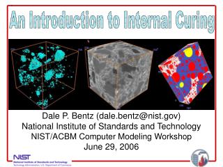
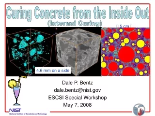
Curing Concrete from the Inside Out. (Internal Curing) . 5 cm . Dale P. Bentz dale.bentz@nist.gov ESCSI Special Workshop May 7, 2008. 4.6 mm on a side. Question: What is internal curing (IC)?

E N D
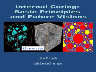
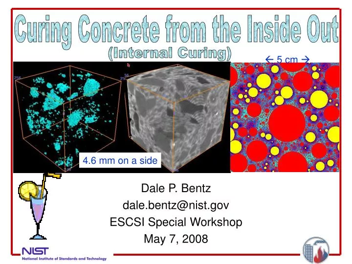
Curing Concrete from the Inside Out (Internal Curing) 5 cm Dale P. Bentz dale.bentz@nist.gov ESCSI Special Workshop May 7, 2008 4.6 mm on a side
Question: What is internal curing (IC)? Answer: As being considered by ACI, “internal curing refers to the process by which the hydration of cement occurs because of the availability of additional internal water that is not part of the mixing water.” For many years, we have cured concrete from the outside in; internal curing is for curing concrete from the inside out. Internal water is generally supplied via internal reservoirs, such as saturated lightweight aggregates (LWA), superabsorbent polymers(SAPs- think baby diapers),saturated wood fibers, or saturated crushed (returned) concrete aggregates (CCA).
Question: Why do we need IC? Answer: Particularly in high performance concrete (HPC), it is not easily possible to provide curing water from the top surface (for example) at the rate that is required to satisfy the ongoing chemical shrinkage, due to the extremely low permeabilities that are often achieved in such concretes as the capillary pores depercolate. Capillary pore percolation/depercolation first noted by Powers, Copeland and Mann (PCA-1959).
Question: How does IC work? Answer: IC distributes the extra curing water (uniformly) throughout the entire 3-D concrete microstructure so that it is more readily available to maintain saturation of the cement paste during hydration, avoiding self-desiccation (in the paste) and reducing autogenous shrinkage. Because the generated capillary stresses are inversely proportional to the diameter of the pores being emptied, for IC to do its job, the individual pores in the internal reservoirs should be much larger than the typical sizes of the capillary pores (micrometers) in hydrating cement paste and should also be well connected (percolated). Internal curing is not a substitute for external curing. As a minimum, evaporative moisture loss (after set) must be prevented using conventional external measures (misting, fogging, curing membrane or compound).
Cement paste Water reservoir
Question: What are the main benefits that IC can provide? Answers: - Reduced autogenous deformation and less early-age cracking •Early-age deck cracking identified as #1 distress in 2003 FHWA Nationwide HPC Survey Results - Maintenance of a higher internal RH, enhanced (long term) hydration and strength development, reductions in creep
A Brief (50 year) Timeline • 1957- Paul Klieger writes “Lightweight aggregates absorb considerable water during mixing which apparently can transfer to the paste during hydration.” in Klieger, P., Early High Strength Concrete for Prestressing, Proceedings World Conference on Prestressed Concrete, San Francisco, CA, July 1957, A5-1 to A5-14. • 1991- Bob Philleo writes “..a way must be found to get curing water into the interior of high-strength structural members….A partial replacement of fine aggregate with saturated lightweight fines might offer a promising solution.“ in Philleo, R.E., Concrete Science and Reality, in Materials Science of Concrete II, Eds. J. Skalny and S. Mindess, American Ceramic Society, Westerville, OH, 1-8, 1991. • Mid 1990s – Research groups such as Weber and Reinhardt in Germany and Bentur et al. in Israel begin to actively investigate internal curing • 1999 – BFRL/NIST enters the arena with the publication of Bentz, D.P., and Snyder, K.A., Protected Paste Volume in Concrete. Extension to Internal Curing Using Saturated Lightweight Fine Aggregate, Cement and Concrete Research, 29 (11), 1863-1867, 1999. • 2000 – In Denmark, Jensen and Hansen conceive the idea of using superabsorbent polymers (SAPs) as internal curing agents • 2004 – Mohr in his Ph.D. investigates saturated wood fibers as internal curing agents; NIST begins active (and ongoing) project specifically devoted to internal curing • 2005 – TXI places 238,000 yd3 of concrete with internal curing (mid-range LWA) in a commercial paving project (railway transit yard) -- Feb. 2007 issue of Concrete Inter. • 2007 – Full-day session on internal curing held at Fall ACI convention in Puerto Rico
A Brief Dictionary(from RILEM ICC committee) • Chemical shrinkage • An internal volume reduction that is the result of the fact that the absolute volume of the hydration products is less than that of the reactants (cement and water); can be on the order of 10 % by volume; ASTM standard test method C1608 approved in 2005 • Self-desiccation • The reduction in the internal relative humidity (RH) of a sealed system when empty pores are generated. • Autogenous shrinkage • The external (macroscopic) dimensional reduction of the cementitious system under isothermal, sealed curing conditions; can be 100 to 1000 microstrains; along with thermal strains can be a significant contributor to early-age cracking
Example of Chemical Shrinkage (CS) Hydration of tricalcium silicate(major component of portland cement) C3S + 5.3 H C1.7SH4 + 1.3 CH Molar volumes 71.1 + 95.8 107.8 + 43 CS = (150.8 – 166.9) / 166.9 = -0.096 mL/mL or -0.0704 mL/g cement For each g of tricalcium silicate that reacts completely, we need to supply 0.07 g of extra curing water to maintain saturated conditions (In 1935, T.C. Powers measured a value of 0.053 for 28 d of hydration – 75 %) Chemical shrinkage of blended cements is generally significantly higher than that of ordinary portland cement
From Chemical Shrinkage to Autogenous Shrinkage • CS creates empty pores within hydrating paste • During self-desiccation, internal RH and capillary stresses are both regulated by the size of the empty pores being created • These stresses result in a physical autogenous deformation (shrinkage strain) of the specimen • Analogous to drying shrinkage, but drying is internal • Autogenous shrinkage is a strong function of both w/c and cement fineness; trends towards increasing fineness and lower w/c have both substantially increased autogenous shrinkage
IC Agent Characterization • Need to assess • Total water (saturated-surface-dry condition) • Available curing water (desorption isotherms) • Particle size distribution (PSD) In final conditions (expanded SAPs, saturated wood fibers) • “Primum non nocere” – in addition to supplying internal curing water, a worthy goal for the IC agent is that it “First, do no harm” to the desirable properties of the control concrete • Physical and chemical stability during mixing, etc.
Sample Desorption Isotherms Saturated salt solutions of K2SO4, KNO3, and KCl Ref: Greenspan, L., Journal of Research of the National Bureau of Standards, 81 (1), 89-96, 1977, see also ASTM C1498.
Concrete Mixture Proportioning For lightweight aggregate (LWA) MLWA =mass of (dry) LWA needed per unit volume of concrete Cf =cement factor (content) for concrete mixture CS =(measured via ASTM C 1608-05 or computed) chemical shrinkage of cement αmax =maximum expected degree of hydration of cement, [(w/c)/0.36] or 1 S =degree of saturation of LWA (0 to 1] when added to mixture ΦLWA = (measured) absorption of lightweight aggregate [use desorption measured at 93 % RH (potassium nitrate saturated salt solution) via ASTM C 1498–04a] Nomograph available at http://ciks.cbt.nist.gov/~bentz/ICnomographEnglishunits.pdf Question of how uniformly water is distributed throughout the 3-D concrete microstructure remains ---- we will come back to this later
Performance Evaluation Question: How can the effectiveness of IC be quantified? Answer: By direct and indirect experimental measurements including – internal relative humidity (RH) autogenous deformation compressive strength development creep degree of hydration restrained shrinkage or ring tests 3-D X-ray microtomography Scanning Electron Microscopy observations
Autogenous Deformation, How to measure it? One way is with custom-built digital dilatometers(Prof. O.M. Jensen - DTU) Paste or mortar specimens sealed in corrugated polymeric tubesand stored at constant temperature Method under consideration for standardization by ASTM C09.68 Equipment now commercially available from Germann Instruments
Autogenous Deformation Results Mortars w/cm = 0.35, 8 % SF
Autogenous Deformation Results Mortars with slag (20 %) blended cement IC added via fine LWA/CCA to increase total “w/c” from 0.30 to 0.38 (0.36) Note – chemical shrinkage of slag hydraulic reactions is~0.18g water/g slag or about2.6times that of cement
Autogenous Deformation of Concrete • Larger corrugated tubes, sealed C1581 rings or .. • Use plastic concrete cylinder molds with a simple dial gauge ---- (similar to creep experiments) Temperature control is critical NRMCA, Dec. 2007
SEM Observations w/cm=0.30, 8 % silica fume IC Control Courtesy of P. Stutzman (NIST) w/cm=0.30, 20 % slag
http://ciks.cbt.nist.gov/lwagg.html Menu for Internal Curing with Lightweight Aggregates 1)Calculate Lightweight Aggregates Needed for Internal Curing 2)Estimation of Travel Distance of Internal Curing Water 3)Simulate Mixture Proportions to View Water Availability Distribution 4)View Water Availability Distribution Simulation Results 5)Learn more about FLAIR: Fine Lightweight Aggregates as Internal Reservoirs for the autogenous distribution of chemical admixtures 6)View presentation on internal curing made at 2006 Mid-Atlantic Region Quality Assurance Workshop Link to Workshop homepage 7)Internal Curing Bibliography 8)Direct Observation of Water Movement during Internal Curing Using X-ray Microtomography
Question:How are the internal reservoirs distributed within the 3-D concrete microstructure? 30 mm by 30 mm Answer: Simulation using NIST Hard Core/Soft Shell (HCSS) Computer Model (Menu selections #3 and #4) Returns a table of “protected paste fraction” as a function of distance from LWA surface Yellow – Saturated LWA Red – Normal weight sand Blues – Pastes within various distances of an LWA
Question: What does the future hold? Answer: - More state DOTs and concrete ready-mix producers will begin to evaluate internal curing (Ohio has done a bridge deck, Indiana and New York are now doing bridge decks) - Investigation of possible “air void” system provided by internal reservoirs once empty - Investigation of possible enhanced workability (retention) and ease of placement in systems with internal curing as reported from the field - Utilization of internal reservoirs for storage of other chemicals besides water (admixtures and phase change materials)
Question: Who (else) is active in this area of research/application? Answer: - NIST - NRMCA (crushed returned concrete aggregates) - NRC/Canada (Dr. Daniel Cusson) - University of Sherbrooke (Prof. Aitcin et al.) - Cleveland State University (Prof. Delatte for Ohio DOT) - Purdue University (Prof. Weiss for Indiana DOT) - RILEM-ICC (Dr. Kosta Kovler – Technion, Israel) - Tennessee Tech Univ. (Prof. Ben Mohr) - Technical University of Denmark (Prof. Ole Jensen) - TXI - University of Michigan (Prof. Hansen) - U.S. Concrete (specified density concrete)